Development of Additively Manufactured Potted Plant Water Wheel
Akshay Kumar, Alex Tanner, Soorya Ramesh
ME514: Polymer Additive Manufacturing
Abstract
We designed and constructed a prototype of a rotating planter that holds several potted plants in the shape of a Ferris wheel. Our intent was to create a design that was both visually appealing and practical, and utilized the strengths of additive manufacturing to accomplish things not possible with conventional techniques. We iterated through several designs for the component parts in order to improve manufacturability and ease of assembly. We were able to create a physical prototype that rotates, as desired, but this concept has opportunities for further exploration and refinement.
Introduction
In the ever-evolving world of urban gardening and modern interior design, there is a continuous search for innovative solutions that combine aesthetic beauty with practical functionality. Our project, titled “Development of Additively Manufactured Potted Plant Water Wheel,” aims to introduce a new concept in plant arrangement that maximizes the use of space while adding a visually captivating element to any room. Inspired by the charm of a Ferris wheel, this rotating planter system is designed to hold six plants, making it a dynamic and attractive piece that enhances the visual appeal of both indoor and outdoor environments.
The cornerstone of our design philosophy emphasizes ease of use and consumer-friendly features, akin to the simplicity of “IKEA style” self-assembly. This approach ensures that anyone can set up the planter with minimal effort, making it as accessible as it is elegant. The design is not only intended to be a beautiful addition to home decor but also practical, as it can be easily relocated to optimize plant growth or adapt to different interior layouts. The rotating mechanism ensures that each plant receives adequate light throughout the day and ease of watering, promoting healthier growth and adding a unique, interactive quality to the user’s experience.
Utilizing the precision and flexibility of additive manufacturing, our project explores the possibilities of 3D printing to create complex and customizable structures that traditional methods cannot achieve. This technology has enabled us to prototype a scalable and adaptable design that can be fine-tuned to meet various needs and preferences. The outcome is a product that is both innovative and sustainable, offering new ways for city dwellers to integrate greenery into their living spaces. As we detail the conception, design, and refinement processes in this report, we highlight the significant potential of additive manufacturing in transforming the way we think about and interact with our natural environment in urban settings.
In the coming sections of this report, we will concentrate on the detailed methodology adopted to develop the “Potted Plant Water Wheel,” as well as the results obtained and discussions surrounding the findings. This breakdown is structured to provide a comprehensive overview of the entire development process, from initial design to final assembly, highlighting key iterations and optimizations made along the way.
Methodology
Initial Design Choices
Once we had come up with the concept, we needed to determine several important parameters before any other progress was made. First was the scale. We decided that we needed to build the structure around the pots themselves. We felt that six pots would be the ideal number, and based on the number and size, that a diameter of 1 foot would be the best for the wheels, since it would provide enough spacing. We also determined how long our axle would need to be based on our pot diameter.
The next matter was that of which process and material to choose. We knew that stereolithography (SLA) or fused filament fabrication (FFF) would be the most reasonable choices for our project regardless. Because the pots themselves would be coming into contact with dirt and water on a regular basis, we initially felt that the continuous surface and structure of SLA would be better for the pots than FFF, since there would be no way for anything to become trapped in the pot itself, which could cause issues with algae or other contaminants down the line. Because the pots did not have any other pressing design requirements, we chose the standard clear resin for its aesthetic potential and lower cost [1]. For the other parts, we determined that FFF could be used in place of SLA, because there was no need to worry about their potential porosity. Because our design was not expected to experience high physical stress, we chose polylactic acid for the filament, since it was not as strong as alternatives such as ABS or ASA, but was more cost effective.
Pot Iterations
The initial iteration of our pot design (see Fig 1) was crafted to accommodate standard succulent pots, measuring 3 inches in diameter. Version 1.0 was produced using an SLA machine with Clear Resin material, resulting in stunningly aesthetic plant pots, as depicted in Fig 2. However, the extravagant cost of $27 per pot and the lengthy six-hour printing time prompted a reassessment of our manufacturing approach. Recognizing the need for a more cost-effective solution without compromising on quality, we embarked on exploring alternative machines and materials to optimize the production process.
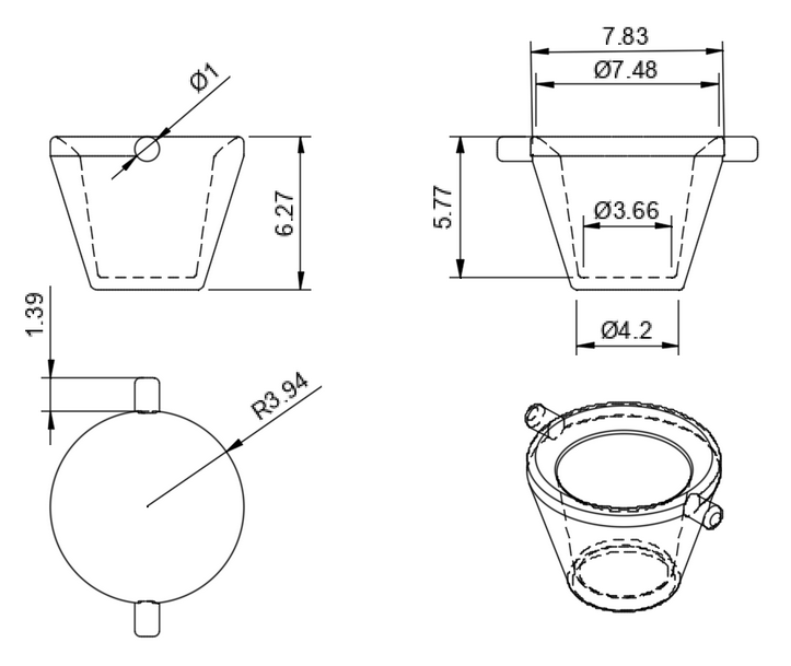
Figure 1. Initial pot design, units of cm
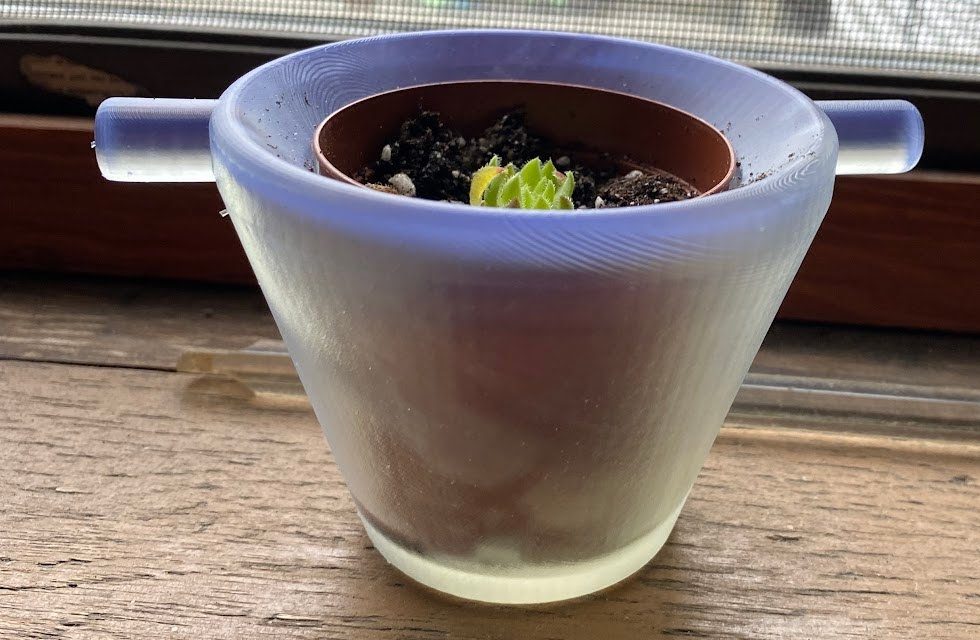
Figure 2. The first pot iteration, with plant.
Version 2.0 marked a transition to utilizing clear PLA (Polylactic Acid) in an FFF machine. While this significantly reduced both the printing time to four hours and the cost per pot to $2.7, as seen in Fig 3, the aesthetic appeal was notably diminished. The translucent nature of the clear PLA did not meet our standards for visual attractiveness, prompting a further refinement of our material choice.
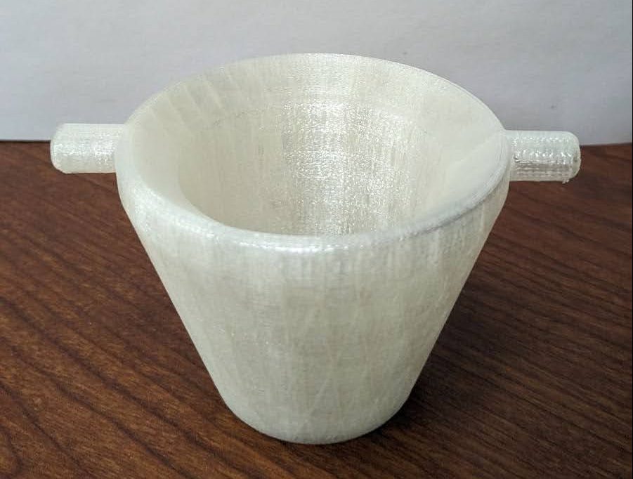
Figure 3. The second pot iteration.
Ultimately, we settled on the reliable option of white PLA material for our pot design, as showcased in Fig 4. By reducing the wall thickness and leveraging the capabilities of the FFF machine, we achieved a balance between aesthetics, cost-effectiveness, and manufacturing efficiency. With a reduced printing time of four hours and a cost of $3.5 per pot, the white PLA option fulfilled our criteria for both visual appeal and affordability. This strategic decision allowed us to maintain the desired beauty of the plant pots while optimizing the production process for mass manufacturing.
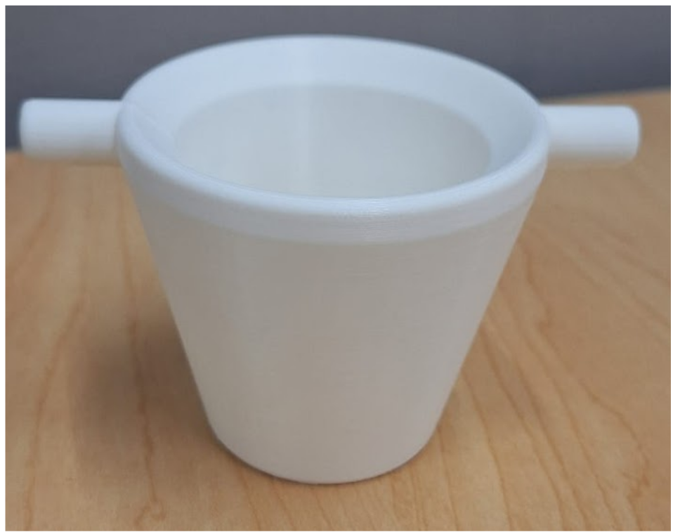
Figure 4. The third and final pot iteration.
Wheel Leg
The wheel legs of our rotating planter prototype represented a straightforward yet crucial element of the design, requiring no iterative adjustments. Crafted from black PLA material, these legs boasted a sleek and durable construction, seamlessly integrating into the overall aesthetic of the planter. With a swift printing time of 1.5 hours per leg and a cost of $3.2 per leg, the choice of material offered a perfect balance between affordability and quality, while ensuring the structural integrity and stability of the prototype. This streamlined approach allowed us to allocate resources efficiently and focus our efforts on refining other, more intricate components of the planter, contributing to its overall success.

Figure 5. Black PLA wheel leg
Wheel
During the development of our rotating planter, we encountered a significant challenge related to the size of the Ferris wheel component. The initial design specified a 12-inch diameter wheel to accommodate the pot sizes, which was ideal for achieving the desired aesthetic and functional balance. However, this dimension presented a logistical problem: the wheel’s size exceeded the build volume of our primary 3D printer, an Ultimaker 5, as illustrated in Fig 7. This mismatch necessitated a reevaluation of our approach to manufacturing the wheel component.
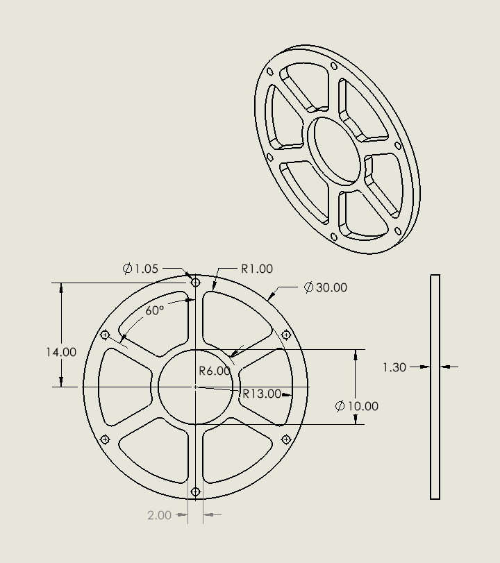
Figure 6. Wheel model version 1
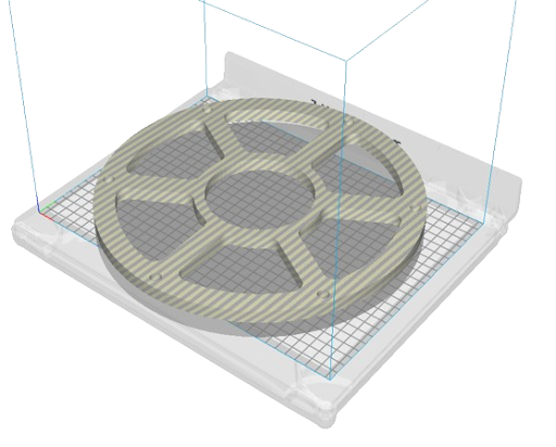
Figure 7. Wheel size on Ultimaker 5
To overcome this obstacle, we considered several alternatives, including scaling down the entire model or altering the design to fit the printer’s capabilities. However, these options would compromise either the planter’s functionality or its visual appeal. Ultimately, we opted to segment the wheel into six pieces, employing a dovetail lock mechanism for assembly as shown in Fig 8. This solution allowed each segment to be printed individually within the confines of the printer’s capacity, maintaining the original dimensions and integrity of the design. Additionally, this method enhanced the manufacturing process by speeding up production and simplifying assembly, enabling us to assemble the full 12-inch wheel efficiently post-printing.
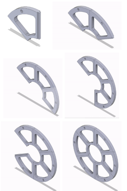
Figure 8. Wheel model version 2
Furthermore, we explored different support structures to optimize the printing process of these dovetail segments as shown in Fig 9. Traditional support structures were initially used, but they required approximately 15 minutes to remove, which was inefficient for our iterative testing process. After experimenting with various configurations, we settled on a tree-type support structure. This adjustment drastically reduced the removal time to less than five minutes per segment. The tree-type support not only facilitated quicker post-processing but also minimized potential damage to the dovetail joints during removal, ensuring a cleaner finish and a more reliable assembly. This strategic choice significantly streamlined our development process, allowing for quicker iterations and enhancements in the design and functionality of the planter.
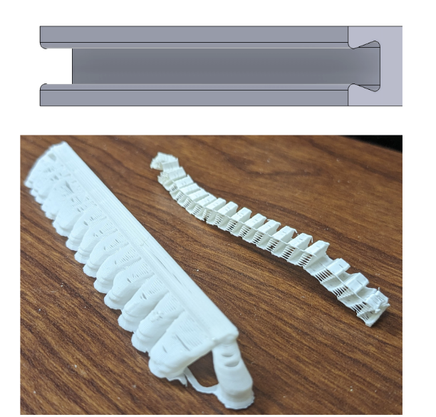
Figure 9. Tree and normal support structures
One-way Bearing
The purpose of the one way bearing for this project was to add stability to the Ferris wheel design. As the name suggests, the bearing only allows rotation in one direction and having them rotate in both ways may cause the pot contents to spill, which would be the case with regular bearing. Several reasons such as cost, structural strength and sustainability [1], makes PLA an attractive choice for the bearings. Being the most complicated parts in the assembly, there were some challenges in 3D printing it. In anticipation of residual material getting caught up between rollers and inner race, The initial design had 1 mm clearance each side of the rollers, as shown in Fig 10. This clearance was a bit too high and thus allowed the bearing to rotate in both directions.
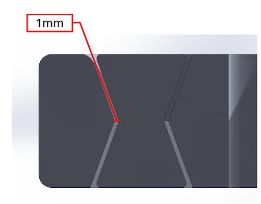
Figure 10. Bearing version 1
In the next iteration, the clearances were reduced to 0.4 mm, as shown in Fig 11. This made the bearing a bit tight to rotate in either direction. From our experience the ideal clearance between the rollers, centerpiece and inner race is estimated to be 0.7 mm on each side of the roller.
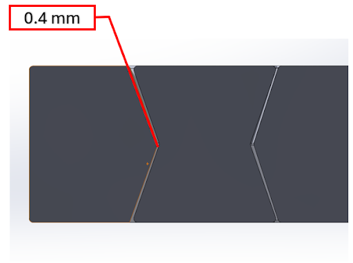
Figure 11. Bearing version 2
Since we oriented it horizontally without any overhangs, there were not any supports in the bearing. There was some residual plastic sticking at the bottom, which was removed with little effort.
Additive manufacturing’s true potential can be realized in parts like bearings, since we don’t have to go through the painstaking process of assembling them. Because of how tight these clearances are between inner parts, it makes more sense to print them rather than manufacturing individually and assemble them. The cost of printing the bearing was only $2.20 and was printed in 3 hours.
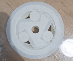
Figure 12. Bearing with residual material
Non-Printed Components
There were a few parts of this project that could not have been printed, either by their very nature or because it was determined to be unnecessary. The parts that fall under the first category are the plants themselves and the soil they were planted in. We chose to use real plants and potting soil in our prototype, since it would give us an accurate idea of what level rotation would be too much for the plants. However, we did not wish to add unnecessary work to this project by using a high maintenance plant species. Instead we used sempervivums, also known as hens-and-chicks or houseleeks. They are very hardy and rarely require water, and large ones (“hens”) regularly produce smaller offsets (“chicks”), which can be detached and planted in new locations [4]. We planted our offsets (see Fig 13) in succulent potting soil in order to improve drainage.

Figure 13. A potted sempervivum offset.
We also chose not to print the axle of our part. We felt that it would be much easier to purchase a cylinder of the proper dimensions than it would be to print it. Print it horizontally, and there would be support material all over one side, which would mar the surface finish and make it harder to determine the tolerances for where it meets the legs and bearings. Print it oriented vertically, and it would be subjected to shear stresses parallel to the layers, which would make it fragile [2]. So instead, we opted for a piece of thin brass pipe cut to length and with a diameter that ensured a press fit with the bearings and legs, as shown in Fig 14. Not every part can be additively manufactured, but those that can, can be designed to interact flawlessly with those that cannot.
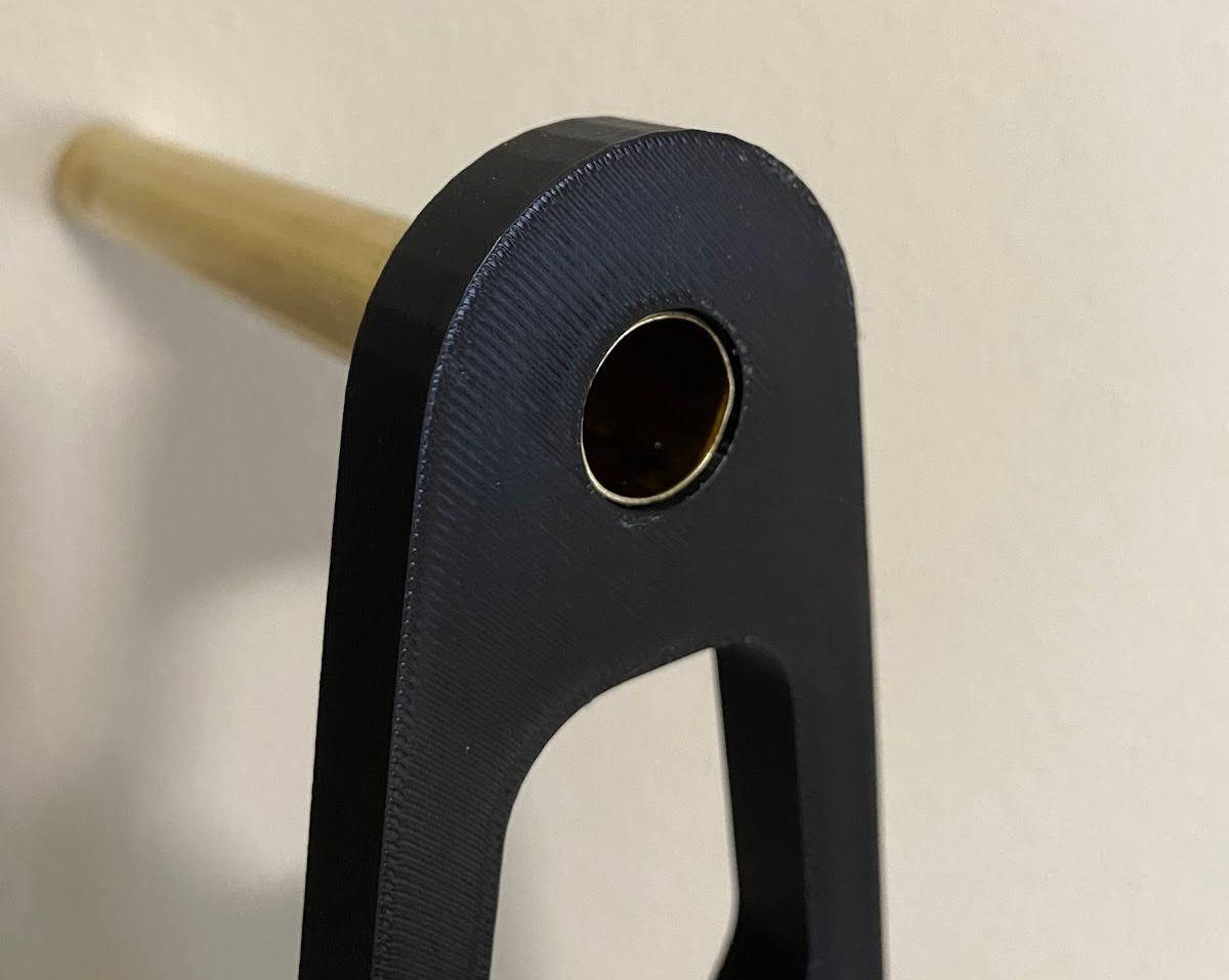
Figure 14. The leg fits snugly onto the axle.
Results and Discussion
The result of the project was successful and the advantages of additive manufacturing were realized. The main benefit was the ease at which complex parts were manufactured. Another advantage was that it allowed us to play with multiple iterations before figuring out optimal design parameters, which wouldn’t be possible with regular manufacturing processes as they would require expensive tool changes. We were also able to understand limitations of 3D printers such as the size limitations and printing duration. Although some of the parts needed minor post processing, the overall assembly worked as intended without any issues.
Post-Processing
Different parts of the prototype required different degrees of post-processing, ranging from none to extensive. Due to the design and orientation of the legs, they required no supports at all and had a smooth surface finish, requiring no post-processing. For the wheel segments, the area of concern was the joints. The wheel segments are joined in a manner similar to a sliding dovetail joint in carpentry, and the resulting geometry is the only part of the wheel itself that requires support. We tried both normal and tree supports, as shown in Fig 15, and found that the tree supports took less time to remove.
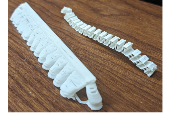
Figure 15. The two types of supports, removed.
The residual plastic in the bearing was removed using pliers and didn’t take much effort. The second iteration of the bearing had tighter clearance and was difficult to rotate. A fine sandpaper was used to sand between the rollers and inner diameter of the outer race. By placing a piece of sandpaper between them and rotating them in the desired direction, we were able to improve the clearance and the bearing was rotating much more smoothly.
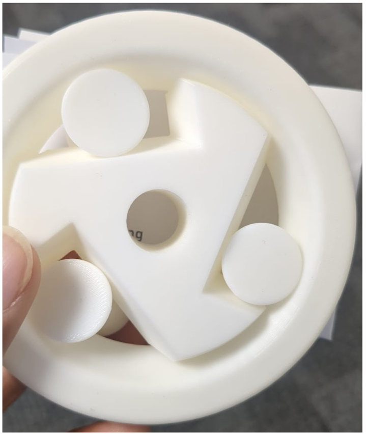
Figure 16. Final bearing
Assembly
The assembly process began as the axle was inserted into the wheel leg, followed by the insertion of a bearing into this assembly. With careful precision, the wheel was then fitted onto the bearing from the same direction, ensuring an interference fit was maintained, thus eliminating the need for adhesives and facilitating future dismantling. Subsequently, the setup was gently tilted at an angle, allowing for the careful insertion of pots pre-filled with plants into the wheel. The remaining bearing and wheel were assembled separately before being inserted as a subassembly into the main assembly, aligning the pots with the other wheel. To secure the components in place, the second wheel leg was added, completing the assembly process.
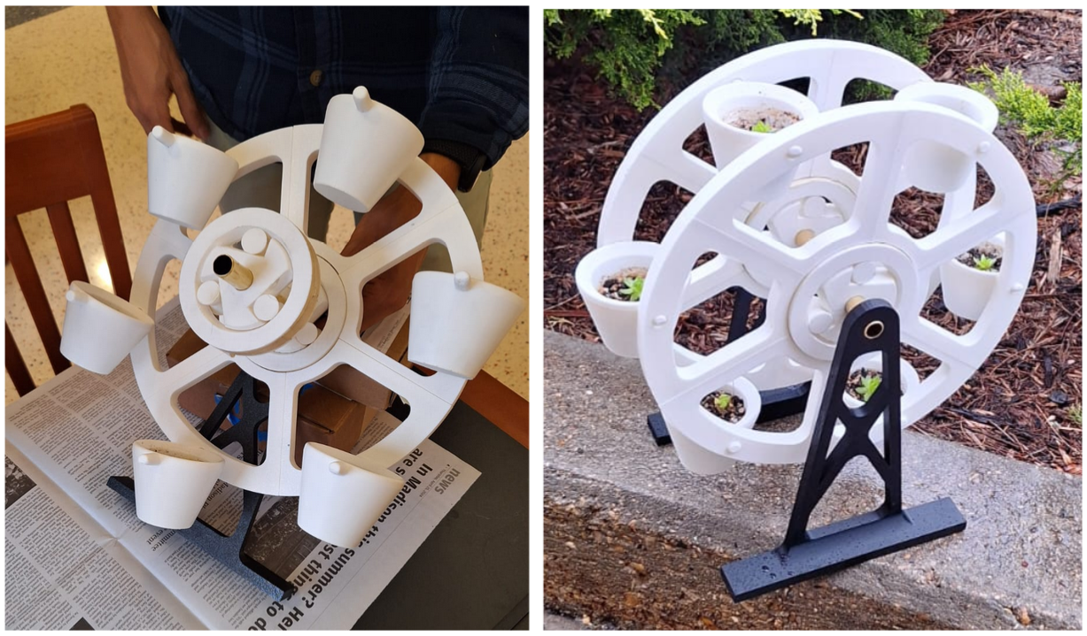
Figure 17. Assembly setup.
Conclusions and Outlook
In conclusion, our project successfully demonstrated the potential of additive manufacturing in creating a rotating planter modeled after a Ferris wheel. By adhering to a rapid prototyping flow chart, our team efficiently navigated the design and production process, enabling quick iterations based on testing and feedback. The result was a functional prototype that not only meets our initial goals of aesthetic appeal and practical utility but also excels in user-friendly assembly, transportation, and disassembly.
Key to the project’s success was our ability to refine the design to enhance usability. The final prototype is easy to assemble without requiring extensive tools or specialized knowledge, which ensures that it can be readily used in a variety of settings, from domestic environments to public spaces. Additionally, the rotating mechanism of the prototype operates smoothly, providing equal light exposure to all plants and ease of watering, which is vital for their health and growth.
Looking forward, there are several identified avenues for improvement that promise to elevate the functionality and efficiency of the planter. Introducing spacers to ensure parallelism of the wheels will ensure stability and uniformity in rotation. Reducing the diameter of the plant pot pegs by 50% will result in much freer movement of the plant pots during rotation. Optimizing bearing clearance will further refine the smoothness of the rotation mechanism, reducing wear and tear, and extending the lifespan of the planter. Additionally, incorporating drainage options will address plant care concerns, making the planter more suitable for a variety of succulent species and environmental conditions [4].
These enhancements will not only improve the user experience but also bolster the planter’s marketability, making it an attractive product for consumers seeking innovative and functional solutions in urban gardening. As we continue to explore these improvements, the project stands as a testament to the utility and adaptability of additive manufacturing in modern design and production, offering a promising outlook for future developments in sustainable and user-oriented product designs.
References
- “3D Printers,” UW Makerspace. https://making.engr.wisc.edu/3d-printers/
- “5.ME514-Processes.pptx: ME514: Polymer Additive Manufacturing (001) SP24.” https://canvas.wisc.edu/courses/396351/files/36066471?module_item_id=6737504
- “Ferris Wheel Plant Stand by BigBricks | Download free STL model | Printables.com.” https://www.printables.com/model/225046-ferris-wheel-plant-stand
- “How to plant, grow and look after your Sempervivum plants,” Talking of Plants. https://talkingofplants.com/blogs/houseplant-and-succulent-care-and-advice/how-to-plant-grow-and-look-after-your-sempervivum-plants