Abstract
Additive manufacturing presents growing opportunities for prototyping within the sport of golf. Traditional manufacturing methods for golf putter heads are labor-intensive, expensive, and time consuming. The use of additive manufacturing, particularly FDM, presents a way to create a cost effective prototype. The primary focus of this project is to produce a custom putter head with reduced manufacturing costs, enhanced customizability, and ease of iteration across various different models. The project developed two design frameworks: 3D scanning of an existing club and custom design using CAD Software. The custom design through SOLIDWORKS was chosen for further testing. Initial iterations successfully produced an aesthetically accurate part. However, the weight of the putter head was significantly less than commercial models and the printing process required supports. The team modified the CAD design and the materials used in the process over a series of iterations. Due to the constraints surrounding the density of available polymers and the size of the putter head, the team used tungsten powder to increase the weight of the part. In the end, the team successfully printed an aesthetically accurate putter head with a weight of approximately 275 grams.
Introduction
Additive manufacturing is a rapidly growing industry allowing for new innovations and improvements in the speed and efficiency of manufacturing. A prominent feature within additive manufacturing is Fused Deposition Modeling (FDM), which is widely used now across both industrial and educational environments. While FDM may not be practical for mass production, it has the capacity to enable rapid prototyping and on-demand manufacturing that traditional manufacturing cannot complete [1].
Golf is one of the most historic sports in the world with its origin linking back several centuries to Scotland. Becoming a new favorite sport across the world, there are many people looking to join the sport. However, the cost of green fees, lessons, and primarily equipment is a common deterrent. Depending on variables such as brand, material, and customizability, a single golf club can cost anywhere between $100 and $500. Additionally, since golf clubs are primarily produced using traditional metal manufacturing methods, it is difficult to secure a low cost prototype model.
The objective of this project is to design a custom putter head that can be designed and manufactured using FDM to reduce prototyping costs and time. Two design capabilities will be utilized: 3D scanning of an existing club and custom design using SOLIDWORKS. Primary goals include reproducing a replica model using polymers, matching the weight of a traditional metal head, and allowing customization of the model for future users.
Design Process
It was first required to acquire a 3D model of a putter head for further experimentation with FDM manufacturing processes. The team explored two design paths in parallel: 3D scanning a reference putter head to create a mesh model, and creating a custom parametric model in SOLIDWORKS. The two models would then be tested and evaluated to determine which design approach yields the best results.
The first design process utilized 3D scanning technology at the UW-Madison Makerspace. The team used a Creaform HandyScan 700 to render a solid model of an Odyssey Toulon – San Diego blade putter head. Due to the geometry of the putter head, two separate scans were required that were then merged into one solid mesh using Creaform’s VX-Elements. The scanning setup and VX-Element software are shown in Figure 1 and Figure 2, respectively.
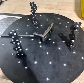
Figure 1: Bottom Face 3D Scanning Setup
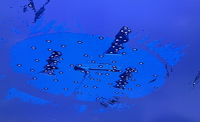
Figure 2: VX-Elements Software Example
Scanning is a relatively quick and simple process only taking around 5 to 10 minutes of time. However, during post-processing, it was shown that the software struggled to differentiate between the color contours of the metallic surface into the matte black surface. Due to this discrepancy, there was significant noise in the background which led to significant difficulties during post-processing to remove the noise and clean the model. The final 3D rendered model is shown in Figure 3.
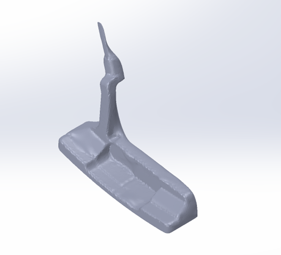
Figure 3: Rendered Solid Model from 3D Scan
The second design process utilized parametric modeling through SOLIDWORKS. The basis for the design was the same Odyssey Toulon – San Diego blade butter but certain liberties were taken for design freedom. The primary constraints on overall size including length, width, and depth were based on governing USGA regulations shown in Figure 4. The critical dimensions for the model are shown in Figure 5 and the initial 3D model is shown in Figure 6. The initial design had a continuous solid body with the hosel directed connected to the top face. As described later in the report, this design was modified to improve printability and aesthetics.
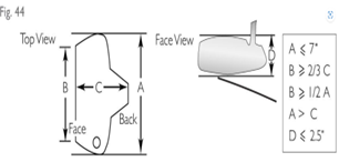
Figure 4: USGA Regulations for Blade Putter
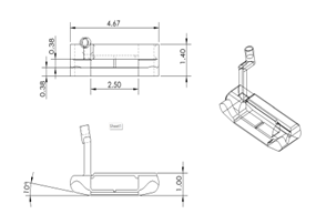
Figure 5: Critical Dimensions for Custom 3D Model
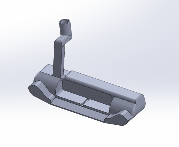
Figure 6: Final Custom 3D Model
Materials & Parameters
The first material used in the FDM printing process was ABS (Acrylonitrile Butadiene Styrene). ABS is a common thermoplastic used in prototyping due to its durability and moderate strength, with a density of approximately 1.04 g/cm³ and a glass transition temperature of around 105?°C. The material is semi-crystalline in nature, which contributes to significant shrinkage during the cooling process. This shrinkage resulted in visible warping of the printed part, especially along flat horizontal surfaces, and negatively impacted dimensional accuracy.
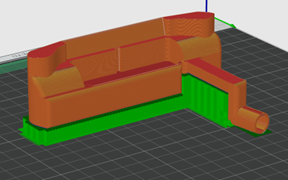
Figure 7: Slicer view of initial prototype
The prototype was printed using a Bambu Lab X1 Carbon 3D printer with a 0.4 mm nozzle, set to a nozzle temperature of 235?°C and bed temperature of 100?°C. The part was printed at 15% infill to evaluate geometry, but the low infill combined with the low material density produced a part that was significantly underweight and structurally insufficient.
A second material was used to improve both print quality and part mass: amorphous-grade polyethylene terephthalate (PET). PET is an engineering thermoplastic with higher density and reduced warping compared to ABS. The specific filament used was selected for its amorphous character, minimizing shrinkage and improving print accuracy. PET has a density of approximately 1.38 g/cm³ and a glass transition temperature between 70 and 80?°C. This version was printed at 100% infill using the same printer and nozzle size, with print settings adjusted to a nozzle temperature of 245?°C and a bed temperature of 80?°C. This print demonstrated improved surface quality, reduced warping, and a noticeable increase in weight, though it still did not meet the target mass of a standard putter head.
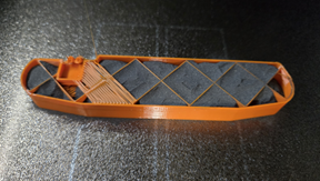
Figure 8: Prototype part with internal metal powder
To further increase the part’s mass, a final version of the putter head was printed using a grid infill structure and filled internally with metal powders as seen in Figure 8. The print was manually paused at predetermined layers to allow tungsten powder and brass powder to be poured into the internal voids before resuming the print. Tungsten powder has a density of approximately 19.3 g/cm³, while brass powder has a density of approximately 8.4 g/cm³. The powders remained loosely packed and were encapsulated by the continuation of the printed outer walls. This process allowed the team to retain the advantages of FDM prototyping while approximating the mass and feel of a commercial steel putter.
All prototypes were printed on the Bambu Lab X1 Carbon system with a 0.4 mm nozzle and a layer height of 0.2 mm. Default print speed was set to 150 mm/s for all builds. Supports were generated automatically in the slicing software to accommodate overhanging geometry, particularly at the hosel. The print orientation was held constant across all trials to ensure consistency in print quality and allow meaningful comparisons across design and material changes.
Results
The first prototype printed using ABS with 15% infill weighed a total of 21.78 grams. While the exterior geometry was reproduced successfully, the part exhibited visible warping due to the high shrinkage of semi-crystalline ABS during cooling. This warping led to a slight lift from the build plate at the corners and a loss of dimensional accuracy along the flat base of the putter head. Additionally, the low infill percentage and low material density contributed to a mass far below that of a commercial putter, which typically ranges between 240 and 300 grams.
The second prototype, printed with amorphous PET at 100% infill, weighed 72.53 grams. This version showed significantly improved dimensional stability and surface finish, with minimal warping and better adherence to the print bed. The increased infill and higher density of PET resulted in a more substantial part, but the mass still fell short of the target weight required to simulate the feel of a regulation putter.
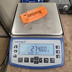
Figure 9: Total mass of the final prototype
The final prototype was printed using the same PET filament with a grid infill structure. Pauses were inserted into the G-code during printing to allow for the manual addition of metal powder into the internal cavities. A mixture of tungsten powder and brass powder was used, with the intention of increasing the mass without altering the print’s exterior geometry. This hybrid print resulted in a final part mass of 274 grams. The outer surfaces remained well-formed, and the internal filling process did not negatively impact the structural integrity or surface quality of the part. The filled grid infill provided sufficient distribution of mass to replicate the balance and feel of a commercial blade-style putter head.
Overall, the iterative material and process modifications led to a functional prototype that met both aesthetic and mass requirements while maintaining printability using a desktop FDM system.
Discussion
The results obtained over the course of this project generally aligned with expectations, with several key insights emerging throughout the iterative design and manufacturing process. The first prototype, printed with ABS at 15 percent infill, clearly highlighted the limitations of using semi-crystalline polymers in fused deposition modeling when dimensional accuracy is important. As anticipated, warping occurred due to non-uniform cooling and shrinkage, particularly along flat base surfaces. This led to a deformed part that, while useful for evaluating general geometry, was not suitable for further refinement or functional testing. Additionally, the low density and infill resulted in a part that was far too light to simulate the feel of a real putter.
In response to these shortcomings, the second prototype used amorphous PET at 100 percent infill. PET was selected for its reduced tendency to warp and its higher density compared to ABS. These expectations were met, as the print exhibited minimal warping and improved surface fidelity. To further improve printability and reduce the need for excessive support material, the hosel was separated from the main putter body in this and all subsequent prototypes. This modification allowed both components to be printed in orientations optimized for surface quality and structural integrity. The separated hosel design proved advantageous for minimizing support structures and simplifying post-processing, while also providing greater flexibility for future testing of different hosel geometries or attachment mechanisms.
Despite the improvements in geometry and print quality, the second prototype still did not reach the target mass. This outcome reinforced a known limitation of polymer-based fused deposition modeling, where even dense thermoplastics cannot match the weight of metal components without additional modifications. To address this issue, the final prototype used a hybrid manufacturing approach that incorporated metal powder infill. A grid infill pattern was selected to create internal voids, and the print was manually paused at selected layers to allow for the addition of tungsten and brass powder. Printing was then resumed to encapsulate the powders inside the structure. This method effectively increased the mass of the putter head while maintaining the desired geometry and surface finish. However, the cost of tungsten powder is relatively high and may limit the scalability of this approach for large-scale or commercial applications where cost efficiency is critical.
The powder-filling strategy proved practical and effective for prototyping, although it introduces potential concerns regarding mechanical stability, as the powders remain loosely packed within the infill cavities. Nevertheless, for the purpose of replicating weight and balance in a prototype, this method provided a functional and accessible solution. The success of the hybrid approach was also enabled by the choice of a grid infill pattern, which allowed consistent powder filling without compromising structural coherence or print quality.
In addition to the physical prototyping efforts, the team also began exploring a parametric modeling workflow in OpenSCAD. This approach would allow end users to adjust key design parameters such as head length, face height, and hosel position through editable variables, making the model more adaptable and customizable. However, due to time constraints and limited experience with OpenSCAD’s syntax, this implementation was not completed during the project timeline. Future work could expand on this effort to enable fully customizable, user-driven putter designs in an open-source format.
Overall, the design and material modifications implemented in this project illustrate the importance of iterative development in additive manufacturing. Separating the hosel from the main body improved both printability and modularity. The integration of high-density metal powders addressed the weight limitations of polymers and demonstrated how hybrid fabrication techniques can be used to expand the functional capabilities of FDM-printed parts. These findings support the potential of desktop 3D printing as a platform for customizable, low-cost prototyping in the sporting goods industry and beyond.
Conclusion
This project successfully produced a low-cost, custom designed putter head using additive manufacturing. Through varying design and iterative testing, the team utilized FDM printing capabilities to ultimately produce a prototype with a mass of 274 grams matching industry standards. If given more time, the group would pursue methods to refactor the CAD model in an open-source site to allow for widespread customization and use.
The work highlights potential opportunities within golf for custom equipment manufacturing. With the improvement of materials in the future, there is potential to produce a functionally and aesthetically accurate prototype with only one primary polymer material. Demand for cost-effective and readily available equipment will continue to rise as the sport of golf continues to grow across the globe. Fortunately, additive manufacturing will assist in the ease of implementation of new manufacturing processes and strategies used to produce this equipment.
References
- Cano-Vicent, Alba, et al. “Fused Deposition Modelling: Current Status, Methodology, Applications and Future Prospects.” Additive Manufacturing, Elsevier, 2 Oct. 2021,
- 4. Clubhead, www.usga.org/equipment-standards/equipment-rules-2019/equipment-rules/part-2-rule-5.html.