Abstract
Focused-ultrasound printing is an innovative additive manufacturing technique that has been developed and research for it is ongoing. This project focuses on the hardware component of studying this technology and creating a watertight vat of high quality while utilizing additive manufacturing techniques learned in class. Results show that FDM printing is not the most viable technique to create the vat especially as PLA and ABS are not ideal for long-term use. The design of the vat will continue to be iterated on for future use and potentially utilizing SLA printing.
Introduction
The resin vat is widely used in light-aided 3D printing such as Stereolithography (SLA) and Digital Light Processing (DLP) as well as Focus Ultrasound (FUS) printing which all require a sealed vat bottom and transparent window for the transmission of light or soundwave. Since the photoinitiator in the viscous ink is extremely sensitive to the light so the bottom of these vat should be as thin as possible to not reflect or deflect any wave. The current resin vat uses Polytetrafluoroethylene or Fluorinated Ethylene Propylene as the bottom which are usually transparent and allows the light to pass through and focus on the surface of material. These materials are usually tough and have high light transmittance which ensures high precision of SLA and DLP printing. In the FUS-printing, the ultrasound has different transmittance in the same medium and the film should be even thinner.
However, since FUS printing hasn’t been discovered until recently, there is not a mature design of the ink vat. The current design contains a hollow frame where both sides are covered by plastic wrap sealing with UV glue. For the research usage which requires repetitive experiment and vat preparation, this design is time consuming and highly varied from batch to batch. Moreover, the plastic has a weak mechanical property and can be easily wrinkled or ripped, resulting in one-time use and dedicated cleanup of the residue of UV glue. In this case, we want to develop an user-friendly, long-lasting and cost-effective ink vat for the FUS-printing applications.
Methodology
For the project, the main additive manufacturing technique used was Fused Deposition Modeling (FDM) printing. FDM printing is the most popular form of additive manufacturing. It is widely used across various industries due to its cost effectiveness, efficiency, and accessibility. With this technique, three dimensional objects are created layer by layer and fusing the materials together. In this process, the printer nozzle melts a thermoplastic filament such as PLA or ABS and extrudes it onto the build platform. For the initial iterations of the project, FDM printing was crucial for rapid prototyping and coming up with a design that was optimal for the vat.
Polylactic acid (PLA) is a material commonly used in 3D printing and manufacturing. It is a biodegradable thermoplastic and offers a promising alternative to conventional plastics due to its sustainability. This material is not ideal for the project due to its biodegradable nature, especially in warmer water conditions. For this project, the water tank will have the same temperature as the human body, which is roughly 36.5–37.5 °C. Moreover, PLA is prone to becoming brittle, lose strength, or warp with prolonged water exposure. Since PLA is an amorphous material, it is not inherently water-resistant. This material was used for printing the initial concept design of the vat.
The second material used for this project is acrylonitrile butadiene styrene (ABS). ABS is a thermoplastic that is also widely used in 3D printing and manufacturing. In comparison to PLA, ABS is better for water exposure, but still degrades over time. Due to its higher glass transition temperature, it also maintains strength and shape better under heat. This material was also tested due to its durability, heat-resistant, and ability to prevent cracks when a clamping force is implemented. Through iterations of the project, ABS was the optimal choice to print the vat as it is still cost effective, without sacrificing any mechanical properties.
Design Criteria
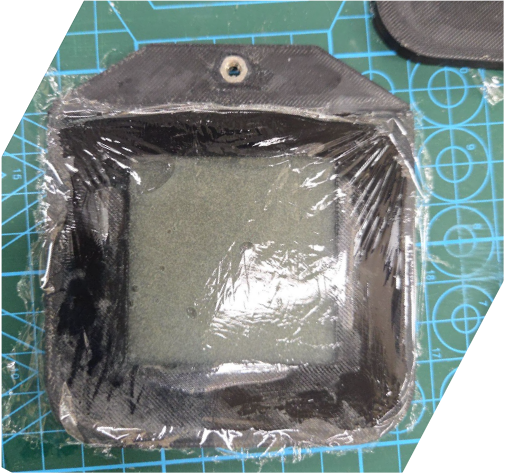
The original ink vat design proved inadequate, primarily due to issues with assembly. It was prone to leakage because the glue failed to form a proper seal, the assembly process was time-consuming, and the film often appeared wrinkled as presented in figure 1. To address these issues, the redesigned vat focused on eliminating these shortcomings. The new design aimed to be watertight, heat resistant, and capable of maintaining high transmittance for focused ultrasound, ensuring improved functionality and reliability.
As previously discussed in the methodology, material selection plays a critical role in the design of the ink vat. The current design utilizes ABS plastic due to its high heat resistance, strong mechanical properties, and long-term durability against water exposure.
Result and Discussion
The results and discussion section will go over the design process, test results, and future improvements.
Design Process
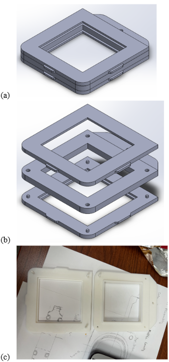
For the first conceptual design of the vat, it utilizes three parts, with the top and bottom layers having the same design and the middle cavity (figure 2). In this iteration, the volume of the empty space in the middle cavity served as a reference for the amount of ink to be filled in the vat. The top and bottom layers were used to simply hold the film in place, with pegs used as alignment for attachment to the middle cavity part. This design also featured a square region for the window, which is optimal in maximizing the amount of surface area of ink to be used.
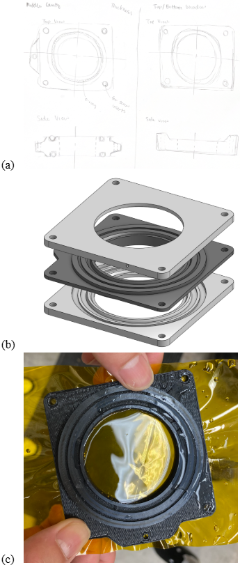
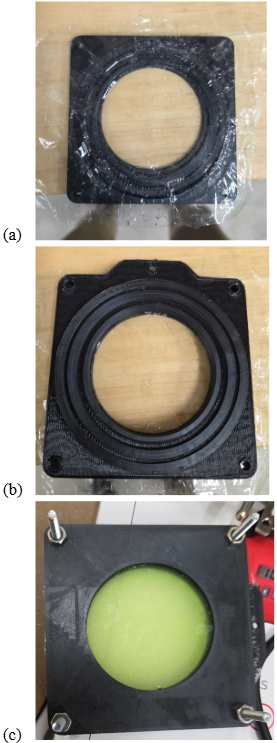
The first iteration of the new design still experienced leakage, necessitating further improvements. In the second iteration, a clamping mechanism using screws, watertight nuts, and a 3D-printed seal was introduced to address this issue. This design features a circular window and two rings that both seal the vat and apply distributed force around the plastic film to maintain tension and prevent wrinkling (figure 3). While this version was nearly watertight, issues with part tolerances emerged. Specifically, the bottom and middle components did not fit properly due to dimensional inaccuracies between the 3D-printed rings. Additionally, the orientation of the bottom part during printing proved critical; if the concave rings faced the print bed, heat-induced expansion caused deformation, preventing a proper fit within the middle cavity. It was also discovered that the thickness of the film prevented the two parts from joining fully.
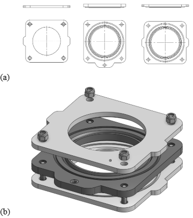
For the current iteration, the top and bottom parts are no longer symmetrical to prevent tolerancing issues when printing the parts. This design is similar to the previous iteration, which can be seen in figure 4. The improved design continues to use screws and nuts to clamp the parts together and prevent leakage. Heat inserts are also melted into the holes of the middle cavity to provide alignment for the parts and screws.
Test Results
The three criteria tested were assembly, film flatness, and sealing. In comparison to the original design assembly which took roughly 10 minutes, the new design took around 3 minutes to assemble. With the sandwich mechanism of the design, the film flatness improved as seen in figure 5. The most important criteria was ensuring there was no leakage, but even with the improved design there still was a bit of leakage, which is still impressive considering there is no actual seal used in the design and mainly relies on frictional forces.
Conclusions and Outlook
In this project, additive manufacturing was leveraged in the design and manufacture of a watertight vat for the FUS printing. The new design replaced the glue-based film deployment and sealing. With the heat insert and the screw sets, the new design significantly decreases time needed for preparation. The optimized mechanical sealing ensures a flat membrane without effort, where the angled rim expands and tightens the film. Though the upgraded design is more efficient, there are still space for improvements.
Firstly, the printing window is circular in present design which provides limited available printing space. In the next design, the printing area will be redesigned into rounded rectangular where larger area can be utilized for printing. Furthermore, the current vat still leaks in a longer term due to the small gap between the parts. This can be compensated by including an O-ring in the next iteration and minimizing any possible leakage. The printing quality by FDM printer doesn’t ensure the designed tolerance and resolution. Since the sealing requires strict gaps, SLA printer will be used to print the design. This will increase the rigidity of the printed parts, thus prevent bending or deformation caused by tightened screw or external forces.
With such a design, we believe that it will boost the iteration of the material in FUS printing and set a foundation for future evolution of the vat design for FUS printing.