ADDITIVELY MANUFACTURED INTEGRATED AIRFOIL FOR ELECTROHYDRODYNAMIC PROPULSION
Khizar Shaikh, Department of Mechanical Engineering, University of Wisconsin-Madison and Immanuel Williams, Department of Electrical and Computer Engineering, University of Wisconsin-Madison
Abstract
This project explores an additively manufactured airfoil integrated with electrohydrodynamic (EHD) propulsion for silent, solid-state thrust generation. Using a topology-optimized design based on the WORTMANN FX 63-137 airfoil, the wing incorporates embedded electrodes to generate ionic wind via corona discharge. The structure is 3D printed to minimize weight and enable modular integration of the power system. This approach demonstrates the potential for lightweight, scalable, and mechanically simple propulsion systems in low-speed aerial applications.
Introduction
Conventional aerial propulsion systems typically rely on mechanical components such as turbines or propellers, which introduce complexity, noise, and maintenance challenges. As the demand for lightweight, silent, and efficient flight platforms grows—especially in the domains of unmanned aerial vehicles (UAVs) and micro-air vehicles (MAVs)—non-mechanical propulsion alternatives have gained research interest. Electrohydrodynamic (EHD) propulsion, which generates thrust through ionized airflow driven by a high-voltage electric field, presents a promising solution. It offers a completely solid-state mechanism with no moving parts, making it attractive for silent, low-speed applications.
This study explores the integration of EHD propulsion within an air foil structure manufactured through additive techniques. By embedding asymmetric electrodes within a 3D-printed wing, it is possible to generate ionic wind and achieve net thrust. The goal of this work is to design, optimize, and prototype an air foil capable of supporting EHD propulsion using topology-optimized structures and additive manufacturing methods. The project combines aerodynamic performance, structural efficiency, and propulsion integration—paving the way for sustainable and scalable distributed propulsion systems.
Design Modification
To support electrohydrodynamic (EHD) propulsion within an air foil, the original WORTMANN FX 63-137 geometry was significantly modified to enable internal integration of high-voltage components while minimizing structural weight. These modifications involved the incorporation of cavities for corona and collector electrodes, insulated routing channels for power delivery, and a re-engineered internal architecture optimized for lightweight strength. A topology optimization approach was employed to reduce material usage without compromising stiffness. The process began with importing the full-span air-foil model into a finite element software where the material properties of the chosen polymer (PLA for additive manufacturing) were defined. Structural boundary conditions such as atmospheric pressure, lift, thrust, weight, and drag were applied, simulating flight-induced aerodynamic loads. The optimization objective focused on minimizing compliance under these conditions while limiting material volume. The SIMP method was used to guide material removal iteratively, resulting in an optimized internal lattice-like structure that aligned with primary load paths. This design not only improved the thrust-to-weight ratio—critical in EHD propulsion—but also ensured manufacturability by adhering to additive manufacturing constraints such as minimum wall thickness and overhang angles. The final geometry was smoothed and exported for fabrication using FDM or SLA techniques. This integrated design balances aerodynamic performance, electrical safety, and mechanical stability in a single monolithic airfoil system suitable for low-speed flight tests.
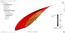
Fig1: – Topology Optimized airfoil
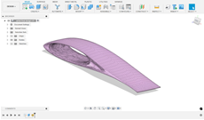
Fig2: – Final Optimized Design
Material Properties
In this project, two additive manufacturing methods were employed to fabricate the integrated air-foil for electrohydrodynamic propulsion: Fused Deposition Modelling (FDM) using Polylactic Acid (PLA) and Stereolithography (SLA) using UV-curable photopolymer resin.
PLA, used in the FDM process, was selected for its ease of printing, availability, and favourable strength-to-weight characteristics. It provided a cost-effective solution for early-stage structural prototypes. The resulting air-foil was notably lightweight, weighing approximately 25 grams, which is advantageous for thrust-to-weight-sensitive applications such as electrohydrodynamic (EHD) propulsion. However, a significant trade-off of FDM printing was the rough surface finish, which can interfere with consistent corona discharge and airflow behaviour. Surface ridges and layer lines were evident, especially around curved geometries, potentially impacting aerodynamic performance.
In contrast, SLA printing using liquid photopolymer resin produced a structurally similar air-foil with enhanced surface quality. The SLA method enabled much smoother external and internal features, which is particularly beneficial for reducing drag and promoting uniform electric field distribution across electrodes. The SLA-printed air-foil weighed approximately 38 grams, reflecting the denser material and solidification process of the resin. While heavier, the SLA air-foil’s high resolution and clean surface finish made it more suitable for final testing and performance evaluation of the EHD system.
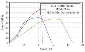
Fig3: – Surface Roughness
Overall, PLA provided lightweight, rapid prototyping, while SLA offered high precision and superior aerodynamic quality. The contrast in weight and surface finish between these two materials played a key role in evaluating the trade-offs between manufacturing efficiency and EHD performance.
Simulation
To evaluate the aerodynamic behaviour of the additively manufactured air foil under low-speed conditions, a 2D steady-state flow simulation was conducted using ANSYS Fluent at a 0° angle of attack. The selected air foil geometry—Wortmann FX 63-137—was simulated with inlet velocity and pressure boundary conditions to assess its lift-generating capability and flow distribution.
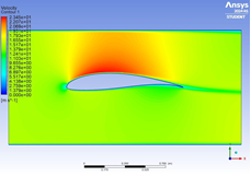
Figure4: – Pressure distribution around the Wortmann FX 63-137 airfoil at 0° angle of attack
Above picture re-presents the pressure contour distribution around the air foil. As expected, a high-pressure region forms near the leading edge on the lower surface, while a low-pressure zone develops over the upper surface. This pressure differential is essential for generating lift, even at zero degrees incidence. The smooth pressure gradient across the chord indicates a favourable laminar flow, validating the aerodynamic suitability of the air foil design for EHD-assisted applications.
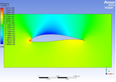
Fig5: – Velocity magnitude contours for the same airfoil under identical flow conditions
Figure 2 shows the corresponding velocity magnitude contours. Air accelerates significantly over the upper surface, reaching peak values just past the leading edge. The velocity gradient confirms Bernoulli’s principle, where higher speeds correlate with the observed pressure drop above the air foil. Flow separation is minimal, and the boundary layer remains attached, highlighting the aerodynamic efficiency of the selected air foil at low angles.
These simulation results verify that the air foil can maintain stable lift conditions at low speeds, which is critical when combined with low-thrust propulsion systems like EHD. The contour plots also help assess optimal locations for integrating electrodes—preferably near regions with smooth, high-velocity flow to maximize ionic wind effectiveness.
Principles of Electrohydrodynamic Propulsion
While a pressure difference across a wing generates the lift needed for balancing gravity, ionic winds are used to provide the thrust needed. It is known that beyond a certain breakdown field strength Ec, air ceases to be an insulator and it conducts electricity. Fig6. illustrates one such phenomenon of corona discharge.
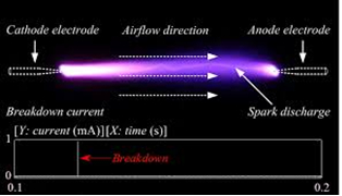
Fig6: – Illustration of corona discharge needed for ionic propulsion. [2]
If the distance between two electrodes with a very high voltage V is given by d, then the current flowing from one electrode to another is given by the following equation[3]:
I = CV(V – Vc) (1)
Where Vc = d×Ec and C = C0l??0/d2 where l is the length of the electrode, ? is the ionic mobility, ?0 is the permittivity of free space, and C0 is a constant that depends on the relative size of the electrode pair. Based on the literature[4], the best value of C0 is achieved when the cathode radius is 12 mm and the anode radius is 25 ?m (which is close to AWG 24 wire). Given the standard values of ionic mobility and by setting d = 10 mm for best results, I = 1.16 mA for a 40 kV power supply. Now, the ionic force density is given by[3]:
fT = ?E = j/? (2)
Where j is the current density and ? is the charge density. For the same test conditions, the thrust force evaluates to 20 mN. Given the limited available literature on electrohydrodynamic modeling, the best reported conditions presented in the literature after experimental characterization are used as a baseline for designing the thrust unit. Therefore topology optimization to reduce mass is essential for reduction of thrust to weight ratio.
Additionally, mass reduction allows the inclusion of of heavier electronic components inside the wing like batteries, high voltage DC-DC converters, resulting in an integrated propulsion unit that does not use long electrical wires, greatly improving reliability and safety when dealing with high voltages. A future objective could involve topology optimization to maximize payload capacity.
Proposed Experimental Setup
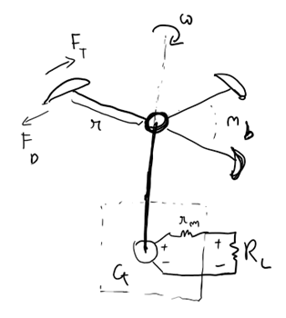
Fig7: – Freehand sketch of experimental setup.
Each integrated wing will produce identical thrust force FT which will be counteracted to some extent by the drag force FD. The resulting force generates a torque which is balanced by the torque produced by a DC generator loaded with a resistive load RL. If the number of integrated wings is nb, the effective distance from the axis to the line of action of the resultant forces is r, angular speed is ?, km is the generator’s machine constant and rm is the generator’s internal resistance, the following equations can be used to size the setup:
(FT – FD(?))×r =km×im (3)
km×? = (rm + RL)×im (4)
By measuring the load current im, one can estimate the angular speed and using CFD tools, estimate the drag force acting on the wings.
Conclusion
While this article explored additive manufacturing techniques needed for aerodynamic-light weight airfoils for electrohydrodynamic propulsion, no physical experiments were conducted. The output thrust to input power ratio has been shown to be more than 20 mN/W[3] which is comparable with electrical aircraft levels but not a lot of research involving payload capacity has been undertaken which is where topology optimization comes into play to reduce the mass of essential but electrically inactive components.
Acknowledgement
Khizar Shaikh – ideation, topology optimization and additive manufacturing study. Immanuel Williams – ideation, ionic propulsion mathematical modelling, electrical system design.
References
[1] B. E. Kelly et al., Science 10.1126/science.aau7114 (2019)
[2] Kang, Yongqiang & Wu, Guangning & Zhang, Xueqin & Guo, Yujun & Shi, Chaoqun & Liu, Yijie. (2018). Polarity Effect of Flowing Air Discharge. IEEE Access. PP. 1-1. 10.1109/ACCESS.2018.2876149
[3] Monrolin, Nicolas & Plouraboué, Franck & Praud, Olivier. (2017). Electrohydrodynamic Thrust for In-Atmosphere Propulsion. AIAA Journal. 55. 1-10. 10.2514/1.J0559288
[4] Eric Moreau et al 2013 J. Phys. D: Appl. Phys. 46 475204 DOI: 10.1088/0022-3727/46/47/475204