Jonathon Semington & Fang-Wei Lee
University of Wisconsin–Madison, Madison, WI
Abstract
This project aimed to improve the performance of a small robotic vehicle by replacing its bulky, overbuilt chassis with a lightweight, structurally optimized version. Using SolidWorks Topology Optimization, we identified regions of non-critical material and redesigned the chassis around essential load paths. The new design was manufactured using FDM 3D printing with PLA, resulting in a 90% weight reduction. We validated the improved design through physical testing, where the RC car achieved a 36% increase in top speed. The project demonstrates how mechanical simulation and additive manufacturing can be combined to produce meaningful gains in real-world engineering applications.
Introduction
As engineers designing for mobile robotic systems, one of the most important metrics we can influence is weight. Excess structural mass not only wastes material but also negatively impacts speed, energy consumption, and maneuverability. For our final ME514 project, we tackled a real-world problem: an RC-style robotic vehicle originally developed by an ECE senior design team featured a chassis that was durable but grossly overbuilt.
Our goal was to redesign this chassis using modern mechanical design tools — specifically topology optimization — to identify and eliminate unnecessary material. We wanted to retain structural stiffness where it mattered while slashing overall mass. Using SolidWorks and FDM 3D printing, we went from a nearly 2-kilogram block to a 100-gram optimized design without compromising component layout or functionality.
This was not just a design experiment — we validated our changes with physical performance testing. The results reinforced our design decisions and proved that digital simulation and additive manufacturing can work hand-in-hand to improve engineering systems.
Original Design and Overbuilding
The original chassis, affectionately called “the tank,” was designed with only one goal in mind: be stiff enough to mount everything. It succeeded — but at a huge cost in weight and material use. Printed with 100% infill and large cross-sections throughout, the Mk.1 design was rigid, yes, but significantly more robust than necessary for the RC car’s actual load case.
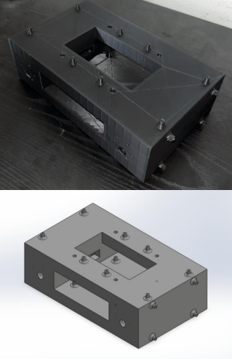
Figure 1. Original Mk.1 chassis showing full infill and dense structure.
This design was fine for early prototyping but unsuitable for performance optimization. The excessive weight hindered acceleration, strained motors, and reduced runtime by increasing power consumption. It also made crash performance worse, since more momentum meant more energy transferred during impact.
Despite these issues, the chassis did have some positive traits. It was dimensionally accurate, easy to assemble, and mechanically secure — making it an ideal baseline for improvement. Rather than starting over, we decided to use its basic form and mounting layout as the foundation for a new, optimized design.
Applying Topology Optimization
To identify where material could safely be removed, we turned to SolidWorks’ built-in topology optimization tool. The process began by applying loads to the chassis where real-world forces would act: the mounting locations for the motors and four control boards. We estimated weight loads based on datasheets, then doubled them using a safety factor of 2 to account for acceleration and handling forces. Fixtures were applied at PEM inserts and motor screw points to simulate realistic constraint conditions.
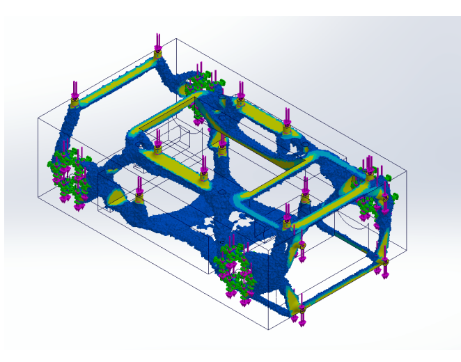
Figure 2. Topology study result showing retained material paths.
The topology result provided a clear visual guide: areas where stress concentrations occurred were marked for material retention, while low-stress zones were flagged as candidates for removal. The resulting “skeleton” of the part showed rib-like structures connecting each mounting point, with arching curves and internal diagonals mimicking organic load distribution.
This output became the backbone of our Mk.2 chassis design. Rather than following the original boxy outline, we carved away large cutouts and preserved only the simulation-recommended load paths.
Redesign and Modeling
Using the topology study as a reference, we remodeled the chassis in SolidWorks from scratch. We kept the key mounting features for motors and PCBs in the same locations to ensure drop-in compatibility. Around those, we created minimal cross-sections and angled ribs that mirrored the simulation’s material distribution.
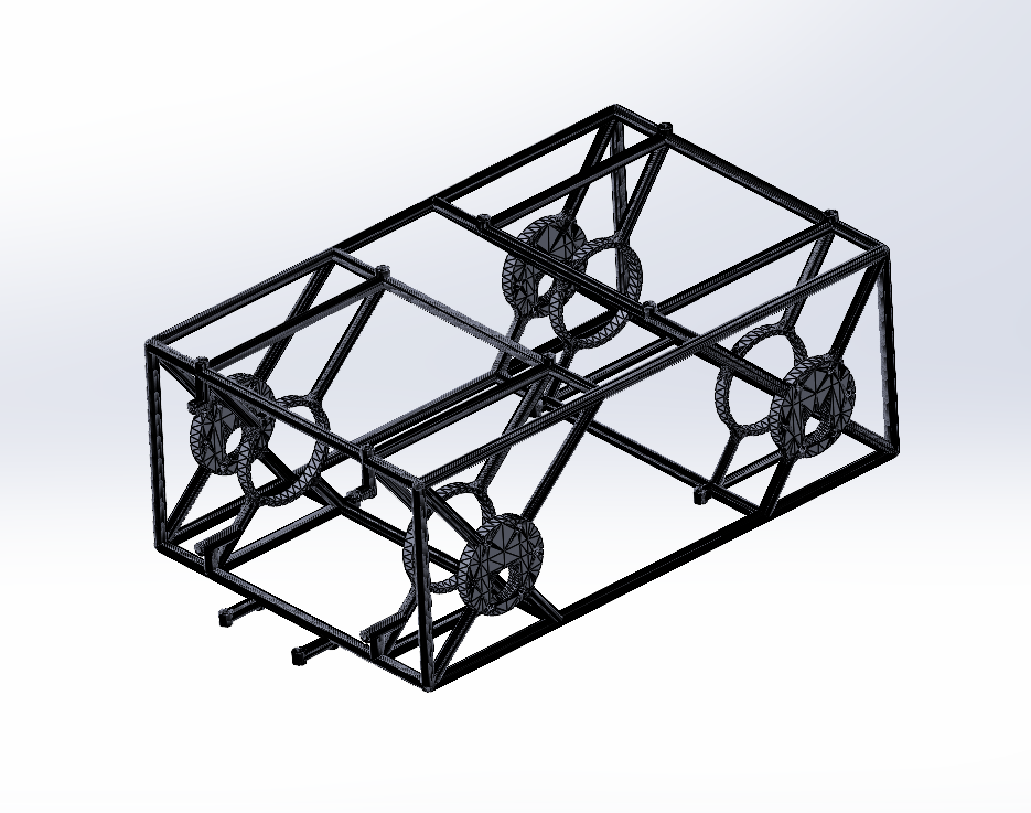
Figure 3. Optimized Mk.2 chassis model.
The design process involved several iterations. We ran design studies to tweak wall thicknesses, test angled rib orientations, and preserve rigidity around key mounting holes. Once complete, we ran a new FEA simulation to verify that the structure could still support the applied loads with acceptable deflection.
In the end, the new design came in at just over 100 grams — a 90%+ weight reduction from the original 1.8 kg block. The part still supported all components, maintained adequate stiffness, and was ready for fabrication.
Fabrication and Assembly
We printed the optimized chassis using a Bambu Lab X1C printer with a 0.4 mm nozzle and 0.2 mm layer height, using white matte PLA. Orientation was carefully chosen to minimize support material while ensuring critical surfaces had good dimensional accuracy. Key print settings included three wall perimeters and 15% gyroid infill, with supports generated only where absolutely needed.
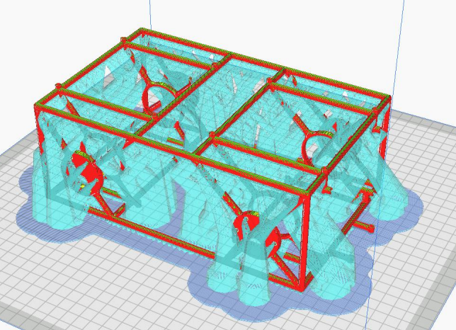
Figure 4. Slicer preview showing support structure for optimized geometry.
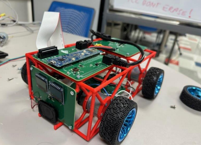
Figure 5: Final RC car assembled with optimized chassis
After printing, we manually tapped the holes for M3 screws and installed PEM nuts where necessary. The part printed cleanly despite its complex shape, and all motors and circuit boards were successfully mounted without needing to alter the layout.
Assembly revealed no major alignment issues, and the printed part held up under light handling and load testing, validating the decision to use PLA despite its brittleness.
Performance Testing
To test the effectiveness of the redesign, we performed a speed test using a fixed 1-foot distance. The car was driven straight across this measured segment, and we recorded the time it took using a smartphone video at 60 fps. Each chassis (Mk.1 and Mk.2) was tested three times under the same conditions, and results
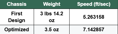
Table 1. Chassis performance comparison.
The optimized chassis was not only lighter — it made the vehicle significantly faster and more agile. Acceleration improved, stopping distance decreased, and the overall driving experience felt more responsive.
Design Trade-Offs and Lessons Learned
Although the Mk.2 design performed well, it wasn’t without drawbacks. The thinner walls and large cutouts meant that the part was more prone to cracking under impact, especially in areas that bore the brunt of cornering or collision forces. In one instance, the chassis cracked after driving into a wall, revealing that our material choice (PLA) might be too brittle for long-term durability.
That said, the simulation-driven structure proved conceptually sound. Stress was directed through the printed ribs and reinforced regions, and no critical mounting points failed during testing. In future versions, we would explore stronger materials like PETG or Nylon, or reinforce weak zones with denser infill or external bumpers.
Conclusions
This project showed that a performance-first engineering mindset, supported by simulation and additive manufacturing, can drive meaningful improvements in real-world systems. By using topology optimization, we transformed a bulky, inefficient chassis into a lightweight, performance-enhancing structure that directly improved the RC car’s behavior.
The redesigned chassis achieved a 36% speed increase while retaining full mechanical functionality. Through careful design, iteration, and testing, we proved that topology optimization is not just theoretical — it can deliver real performance gains when paired with practical fabrication methods.
Acknowledgments
We would like to thank the UW Makerspace for providing 3D printing and fabrication resources. We’re also grateful to the ME514 course staff for their guidance throughout the project. Lastly, thank you to the ECE Omni-Rover design team for their collaboration and system integration support — and congratulations to them for winning Best Project in their senior design course for the Omni-Rover platform.