Adjustable Laptop Stand
Logan Balliett, Christine DeMarchis, Erin Williams, Natalie Rullman
Abstract
This report explores the utilization of Fused Filament Fabrication (FFF) and Stereolithography (SLA) techniques in the fabrication of an adjustable laptop stand. The primary goal of this project was to design a user-friendly laptop stand that could be easily printed and assembled without additional tools required. Additive manufacturing is a tool that revolutionized the production and manufacturing of complex geometries with minimal material waste. With this, the primary objective is to achieve minimal material consumption while ensuring high structural integrity and thermal durability.
This study investigates design parameters, material properties, printing strategies, and cost effectiveness for an adjustable laptop stand. FFF is a widely accessible printing method and is budget friendly. SLA on the other hand, is known for its high precision and surface finish. Combining these two methods will allow for an economic product while achieving the desired outcomes.
The experimental results demonstrate that selection of materials, layer thickness, infill patterns, and printing parameters significantly influence the material efficiency and mechanical properties of the stand. The findings highlight the potential of FFF and SLA in creating lightweight, yet robust structures with minimal environmental impact.
Introduction
This project aims to create an adjustable laptop stand using SLA and FFF printing technology. Our goal is to produce a stand that is customizable to the user as it can withstand many laptop models and rack applications. Our design will allow independent adjustment of the legs which can alter the angle at while the stand sits and the overall height of the stand. The design of our adjustable laptop stand will minimize material usage while still maintaining structural durability to ensure a wide range of laptops can be held.
Materials
From the project proposal, we had discussed the use of SLA rather than FFF. We decided to use FFF for the initial print as it is faster and not the end use product. After considering our design, we decided to continue to use FFF as the method for the laptop stand as it has a higher strength. For our FFF prints, we used PLA because of its high strength compared to ABS. We assumed that the highest temperature that a laptop would achieve would not be enough to cause concerns for thermal degradation of the PLA. For our first print, we used the Bambu printer, and for our final prints we used the Ultimaker printer in the makerspace. To mitigate slipping of the legs on smooth surfaces and the laptop on the stand, we planned to use SLA. We believed that flexible resin or elastic resin would be a suitable material to keep the laptop stand from slipping on most surfaces. After analysis of the different material properties of flexible and elastic resin, we decided to print the non-slip parts with flexible resin. These added parts are further discussed in the redesigns and future trials.
Prototype Print Trial
For our first printing trial, we printed the plate and one set of each size leg/foot pieces. Shown below in table 1 are the printing times for our first print trial. The parts for the first printing trial cost $12.89. If we were to have printed all four legs instead of just two, the cost would increase to $19.89. Overall, the print trial was a success for the prototype. Most of the concepts behind our laptop stand design proved valid when printed using FFF techniques with PLA as the material of choice.
Table 1. Print times for first prototype.
| Part (# of prints) | Time |
| Top Plate (1) | 13 hours |
| Top Leg Pieces (2), Bottom Leg Pieces (2),
Foot Pieces (2), Pins (2), Pin Locks (2) |
4 hours
(one build plate for all pieces) |
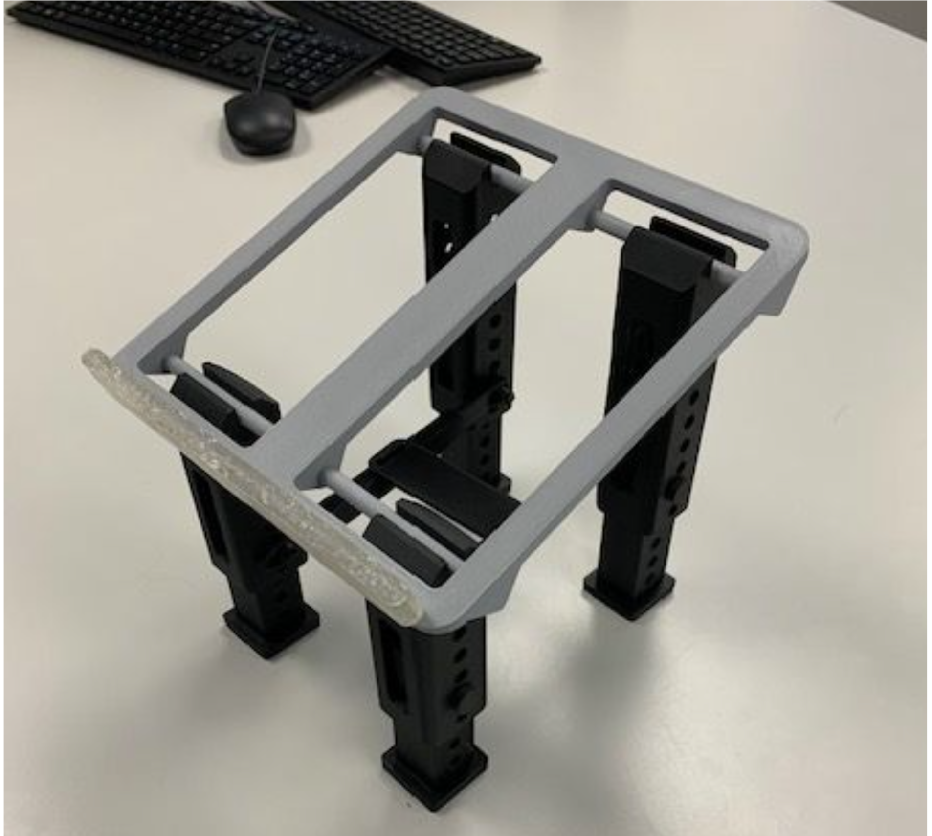
The design of the legs worked well, with the telescopic leg and pin system functioning as designed, allowing the leg height to be easily adjusted through the position of the pin. Additionally, the foot pieces on the bottom of the legs had a snug fit with the bottom leg pieces. Another positive is the snap fit of the top piece of the legs onto the rod of the laptop plate. The open slot at the top of the legs slides over the horizontal rod with reasonable force, requiring no tools, and only a small push with one hand while the other hand holds the plate. Once together, the plate will not easily separate from the legs unless the same intentional force is used, preventing accidental separation of the assembly.
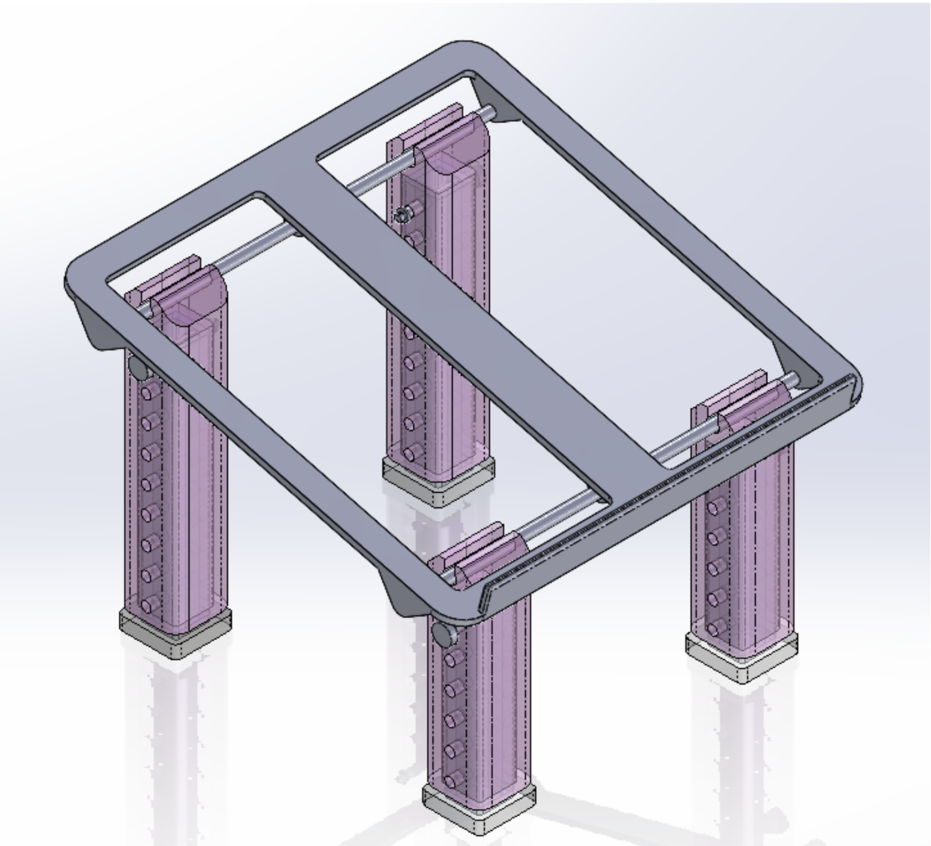
Figure 1. Isometric View of Full Assembly.
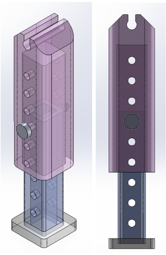
Figures 2.a./ 2.b. Isometric view and side view of a front leg assembly.
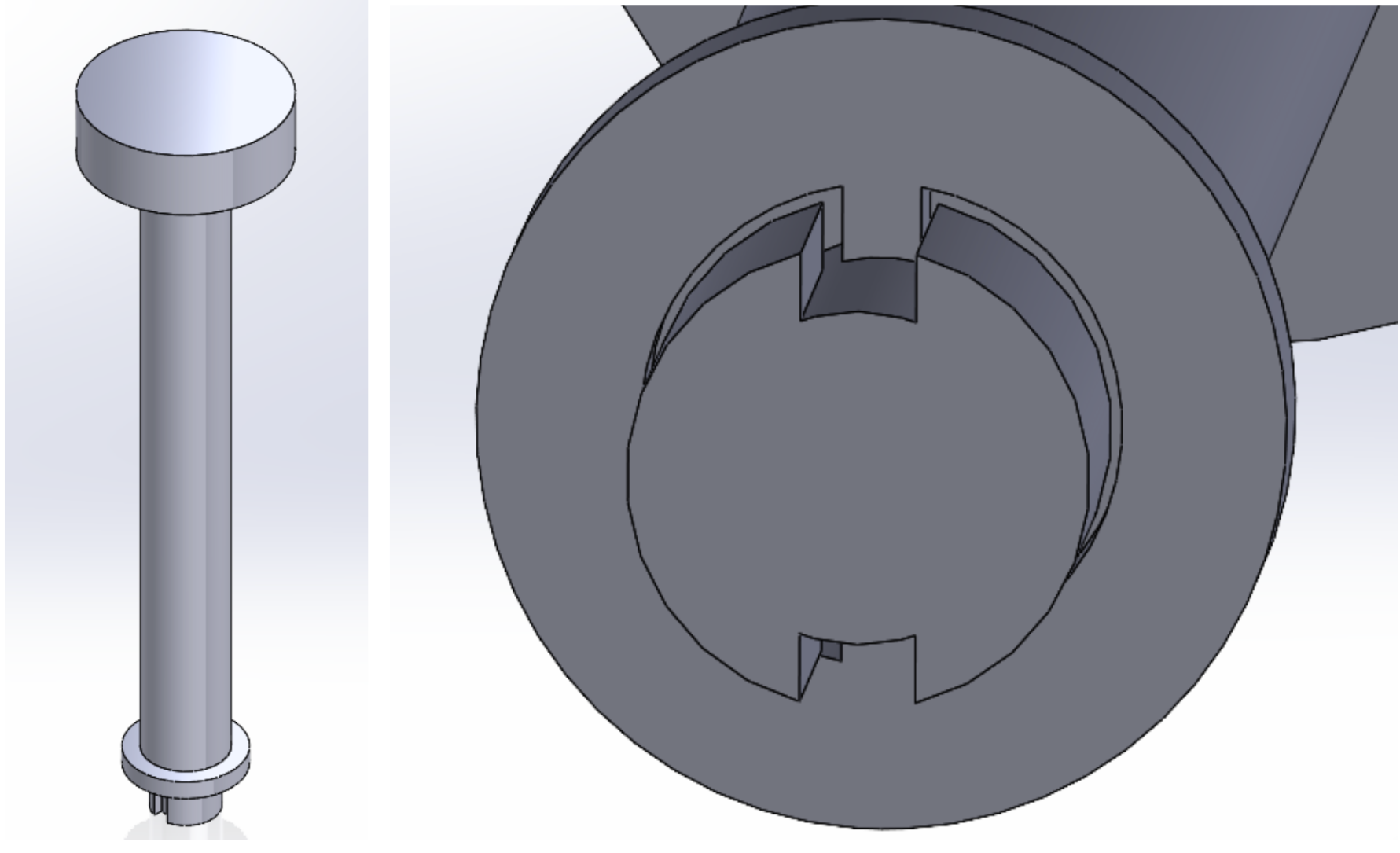
Figures 3.a / 3.b. Isometric View of pin and lock assembly and close up view of the tooth and slot mechanism.
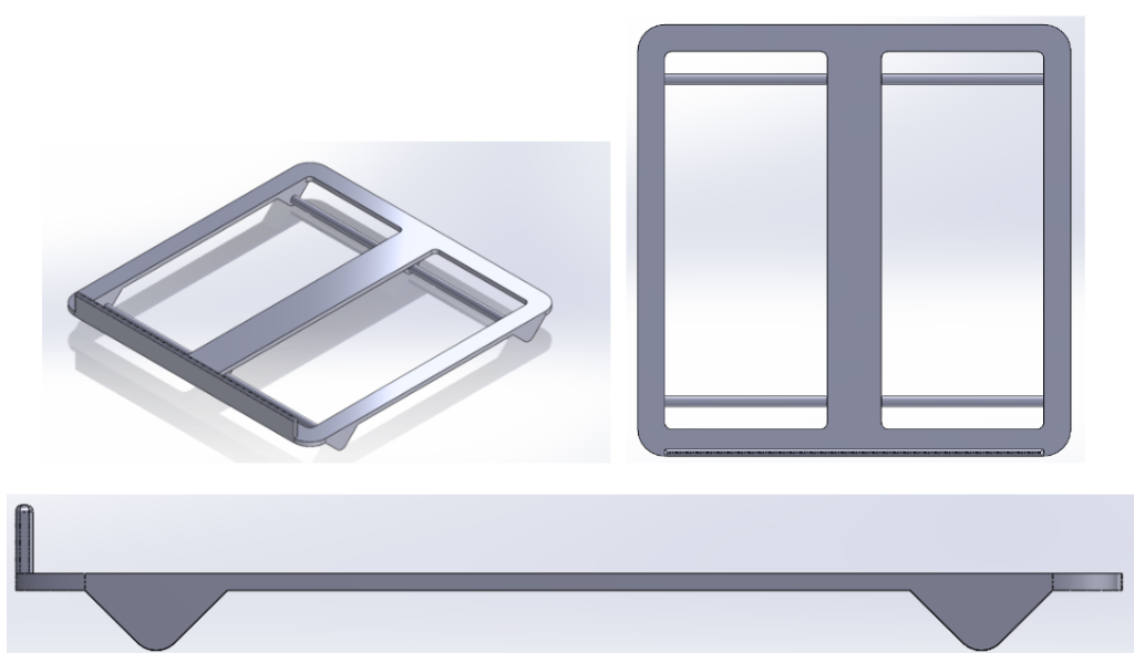
Figures 4.a. / 4.b. / 4.c. Isometric View, Top View, and Side View of the laptop plate.
The main aspect of our design that needed improvement is that the legs and stand weren’t as stable as we’d like. The leg pieces have too large a clearance between them, leading to instability and wobbling. This problem worsens as you extend the legs to be taller, and the legs become very unsteady. As well, the plate of the stand is loosely attached to the legs, causing more shifting once the stand is assembled. Although the legs snap around the plate rod nicely, the rod is too loose once it is inside the leg housing, allowing for too much movement in the connection. The pin locking mechanism also has similar issues to the leg and plate snap fit issue. The tooth and slot design of the mate proved conceptually valid, but the dimensions of the features were too small for the resolution of the printer, resulting in inaccurate printing of the geometry. Another area that needed reimagining is how best to orient the prints or to change the design of the plate and outer leg pieces to reduce supports, or make removing supports easier.
Redesigns
The primary redesign goals for the final print were to increase the stability of the structure, and the FFF printing performance of the parts. The specific printing performance parameters targeted were the resolution of the smaller parts, and the ease of removal of support materials.
The first step towards increasing the stability of the laptop stand was the modification of the leg components of the stand. All three pieces making up the leg subassembly, including the foot, bottom section, and top section of the leg had their cross-sections modified to be larger. All three pieces remained the same square shape, but gained roughly 0.25 inches in side length of the square cross section. In addition to the scaling of the cross section, the clearance distance between the two telescopic leg pieces was reduced significantly to remove unwanted wobbling that occurred between the two telescopic pieces.
Another action taken towards increasing stability was the design of interconnecting cross brace pieces that help immobilize the legs during use. The cross bracing pieces were designed to be simple and use as little material as possible. To achieve this they were designed to connect to the pins that are already in use for the legs. This gives the cross pieces a simple method for attachment to the structure, and reuses the existing pins, which eliminates the need for even more additional pieces.
The main components of the stand that required alteration for better FFF performance were the leg pins and the coinciding locking pieces. In the first print trials both sets of these components were printed without much of the fine detail required to make the locking mechanism function properly. This was due to the geometry having a more fine resolution than the Ultimaker printer could produce. The solution to this issue was to scale up the dimensions of both the pins and the lock pieces. The geometry of and function of the two pieces was kept similar in the design revision, however most dimensions were simply increased in scale to allow greater room for error in the 3D printing process. The other redesigns focused around improving FFF performance was the modification of the leg pieces and plate piece to make the removal of support material easier. The support material inside of the top leg pieces was very difficult to remove in the first iteration. The redesign of the top leg pieces used cut-outs in the body of the leg to add access points for support removal. The addition of the cut-outs would not cause any significant change in the strength or function of the legs, but they would greatly increase the ability for tools to be used to scrape support material from the inside of the legs.
The other printing performance based design changes took place in the plate piece of the laptop stand. The main concern in this part was the removal of the support material without damaging the part. In the first print the support materials were removed successfully, however large force was required, and there was considerable risk of fracturing the thin cross-sections of the plate. To avoid this, most of the cross-sections of the plate were increased by 0.125 – 0.25 inches, and some of the more complex shapes of the plate were revised to simpler geometries to reduce the areas in which support material was needed.
The last design revision after the first print trial was the use of flexible resin to create a non-slip sleeve that could be attached to the lip of the laptop plate. Testing of the first print trial proved that the interaction between the laptop and the plate could be quite slippery with the PLA material used. To prevent slippage, a flexible resin sleeve, printed using SLA, was designed to slide over the front lip of the plate to increase friction and reduce slipping between the laptop and the stand.
Final Print
The final print of the laptop stand components presented more error than the first printing trial. During the printing process the top leg pieces for the back legs printed poorly, however the shorter version of these pieces used for the front legs printed correctly. This was a strange error as the only difference between the front and back leg version was the total length, however the printing error was not related to the length of the parts. Regardless of cause, this poor printing required a reprint of the top leg sections for the back legs. Another printing error occurred in the SLA process to produce the non-slip sleeve. This part failed multiple times, with the printing process struggling to produce the thin slit that was designed to fit tightly around the lip of the laptop plate. The flexible resin feet also failed to print, so we kept the FFF feet to use in our final prototype.
The final print took longer than the first print, predominantly due to the size increase of the leg pieces and the addition of the flexible resin sleeve. The printing times for each part are shown below in table 2. This print cost a total of $27.59 for all the pieces involved.
Table 2. Print times for the final print.
| Part (# of prints) | Time |
| Top Plate (1) | 13 hours |
| Top Leg Pieces (4), Bottom Leg Pieces (4),
Foot Pieces (4), Pins (4), Pin Locks (4) |
30 hours
(one build plate for all pieces) |
| Cross Bars (2), Connector (1) | 2 hours
(one build plate for all pieces) |
| Non-slip Sleeve (1) | 14 hours |
Apart from the failed prints, the component redesigns were mostly successful. The reduction in clearance between leg pieces greatly reduced the amount of wobbling of the structure, and the cross-bracing pieces did increase the stability of the legs. The increased size of the pin and lock mechanism also improved the printability of the two parts. In the final printed trial both of these components printed with the desired geometric resolution. The non-slip sleeve printed with the flexible resin was also successful in its design intent by fitting tightly to the lip, and providing a more sticky surface for the laptop and stand interface. The final printed version of the full assembly can be seen in Figures 5.a., 5.b., and 5.c.
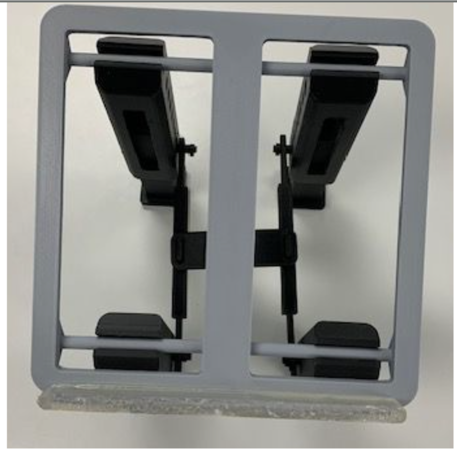
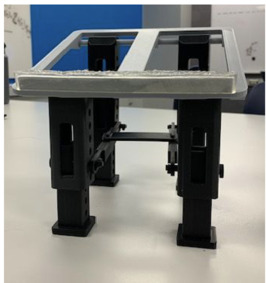
Figures 5.a. / 5.b. / 5.c. Isometric view, top view and front view of redesigned laptop stand.
Future Revisions
Despite successes with our final design and prototype, there are still many improvements that could be made for future iterations of the laptop stand. Potential revisions include redesigning to increase stability of the stand, optimizing the design for efficient FFF printing, and cosmetic upgrades.
Most importantly, some aspects of the design could still be made more stable by decreasing clearances between parts. The design of the leg pieces could be improved to have a smaller clearance with the rod on the plate, in order to prevent the legs from shifting easily on the rods. Another idea for this concept is to make the rod square instead of round. This could prevent rotation of the legs around the rods and increase overall stability. The length of the pins could be decreased as well to prevent sliding, as well as hold the crossbars in place.
Creating the flexible SLA feet for the design would also increase the stability of the laptop stand. Since these failed to print properly when we attempted to print, perhaps redesigning would be necessary to have a successful print. Printing with a different orientation could also potentially solve this problem. Either way, adding the flexible resin feet to the design would add stability to our design by ensuring the stand wouldn’t slip on different surfaces.
Also involving the legs and plate, we noticed that at large tilt angles, the plate interferes with the top of the legs, making it so the rod can’t fully insert into the slot on top of the legs. Moving the rod position on the plate design could easily solve this problem for future prints.
Another feature of the laptop stand that can be improved is optimizing the design for quick and easy FFF printing. While we managed to print all components for the stand, there were issues along the way with failed prints and removing difficult support material. Additionally, some of the components of the stand, like the leg pieces, for example, took a very long time to print and were rather expensive.
Optimizing the design of the legs and other components could make the printing process much easier, faster, and less expensive. This could include performing finite element analysis on the leg pieces in order to remove unnecessary material, and intentionally redesigning to reduce supports necessary. Choosing optimal printing orientation is also an important step to take in this direction.
Lastly, there are a few cosmetic revisions that could be made to improve the quality of the laptop stand. The flexible resin sleeve provided its intended function, but it could use additional post-processing to make the top surface smoother. As well, some aspects of the design are bulky and could be made sleeker. The legs of the stand could be made to use less material, though testing would be necessary to ensure that they don’t sacrifice stability or strength.