Abstract
The Fused Filament Fabrication (FFF) additive manufacturing process was used to create a travel-sized chess set. This design was created entirely from scratch, incorporating known concepts and popular methods, such as hidden magnetic pieces, along with novel concepts, such as transformable pawns. The final design represents a chess set that closely mimics the experience of using a fully-sized wooden chess set while incorporating additional benefits relating to portability and convenience. This was all achievable with the 3D printing resources available in the UW-Madison Makerspace. Overall, the project was a success due to steady progression, reaching major design milestones well before the project deadline. This allowed time to make minor changes, optimize printing settings, and add aesthetic features to the final design. Ultimately, every major design idea was realized and the required 3MF files were all set for an end user to send files to an FFF 3D printer and have a finished, professional quality product.
Introduction/Project Overview
Preliminary Designs
The initial designs were hand sketches and they are shown in Figure 1 below:

Design and Manufacturing
Several constraints were set for this travel chessboard design to ensure its functionality. Dimensional constraints were largely dependent on the height of the pieces, as the pawns incorporated a mechanism to expand into other full-scale counterparts. The correct piece height was chosen to ensure they were easy to handle while fitting into a travel-sized box. The height of the pieces also affected the size and clearance required within the box. Regarding material selection, the chosen material must have been strong enough to withstand the force associated with the transforming mechanism within the pawns, as outlined in the initial material selection process. The limitations of the additive manufacturing process guided the pawn design along with its assembly. Features with significant overhangs such as the bar in the pawn mechanism or the recess for the magnets were changed to accommodate the printer’s capabilities.
Initial methods and materials
FFF printing with PLA thermoplastic material will be used for the first attempt/prototype due to the higher material strength/rigidity as compared to other printing methods and materials. Additionally, PLA is known to be the most readily available and cheapest material to 3D print with, making it the most attractive candidate. The material strength of PLA was more than sufficient for the internal mechanism of the chess pieces, and this was tested in several experimental trials. This method of printing was used for the pieces and the box to house the board.
Trials and Experimentation
Several key principles needed to be tested before printing the final assembly. The first and most critical concept was to validate the size of the pieces along with the pawn’s mechanism used to transform them into their respective larger pieces. Experimentation was carried out on the degree of portability of the design. This included fitting the product in several different common bags and commenting on its degree of comfort. The magnet’s strength is another concept that required validation, as the magnets must have been strong enough for the board to hold the chess pieces in place at any orientation. In addition, they should have been light enough for the user(s) to move, remove, and place the chess pieces into their respective positions while interacting with them. The strength of the bar that acts as the swivel point for the transformable pieces must have also been tested to ensure it would withstand the stresses of normal use. Choosing the appropriate tolerances for the FFF 3D printer being used was another important consideration in the test prints. The press fit of the box itself needed to be tested along with that of the magnets. Both of these required tuning the tolerance for press fits and were essential to the product for both the aesthetics as well as eliminating the need for fastening methods in the assembly process.
Design Process
Design Dimensions:
Design dimensions for the box and piece diameter were guided by the 256 mm x 256 mm Bambu Lab X1 Carbon textured PEI print bed. A width of 240 mm for the box was chosen to fit within this bed and have tolerance for potential future redesign decisions. The usable chessboard area fits within this box, having dimensions of 230mm x 230 mm, which leaves a 28.75 mm x 28.75 mm box for each piece. The diameter of the circular inlay for each piece is 23 mm, and the diameter of the base of each piece is 22 mm. The associated tolerance of the pieces as they fit into this inlay was tested and is explained in the testing section below. The maximum height of the pieces was chosen to be 40 mm to ensure the inside of the box can accommodate the various piece heights when it is closed. These key dimensions can be seen in Figure 2.

Initial Box/Board Design:
The printable area of the Bambu printer sets the dimensions of the outer shell of the box. This then set the dimensions of the area that the board could take up. Using the board base dimension and the relationships established by a chess board (ie, 8 tiles in both directions), the dimensions of an individual tile could be determined. However, since two different colors were desired, and direct side contact was a feature that was not wanted in an FFF print. So a smaller tile centered on a full-size tile was added to ensure slight gaps to their nearest neighbors. This two-tiered design can be seen in Figure 5. Where the bottom portion was the entire board area with intermittent smaller portions on the top for the actual playing surface which will have the desired gaps. The entire board can be seen in Figure 4. This board now has to fit into a box and the box has a slight cut-out to ensure that the board does not shift around during transportation. The board inside of the box can be seen in Figure 3. The cut-out for the board to slide into can be seen in Figure 6.


Initial Transforming Pawn Design:
The pawn pieces consist of many transforming mechanisms. It was designed to be aesthetically pleasing, easy to transform, and printer-friendly. The initial design of the rook pawn and the detailed transformation steps are shown below in Figures 7, 8, and 9..


Figure 7: The pawn piece in its pawn form and rook form.


Figure 8: The pawn piece’s components: a. Rook top; b. Rotation axis; c. rotating outer shell; d. Pawn base 1; e. Pawn base 2.


Step 1: Rotate the shell 90 degrees until the slots match
Step 2: Flip the rook top piece 180 degrees
Step 3: Rotate the shell 90 degrees to hide the empty space of the pawn base.
Figure 9: The pawn piece’s transformation steps.
Initial Piece Design:
Design dimensions for the pieces were ultimately guided by the Bambu Lab X1 Carbon printer bed and the height of the box. The base diameter of 22 mm and the general base shape design for all pieces were both the same. The pieces were modeled with classical chess piece designs in mind but with fewer small features and more emphasis on smooth curves. All 5 CAD models that were created are shown below:


Figure 10: From-scratch designs of the king, queen, bishop, rook, and knight
Every piece except the knight was completed using a revolve feature, with the king’s cross being made with an extrude feature. The knight was more complicated to model, using a combination of revolve and loft features. An early screenshot of the knight modeling process is shown below:

Estimates regarding minimum feature sizes were made, such as the knight’s eye, king’s cross, and bishop’s button. The results of these design decisions as they were printed are discussed in the testing section below. The pieces were also designed to have varying heights, with the king and queen being the tallest, then the bishop, knight, and rook in order from tallest to shortest.
Initial Testing
The initial designs of the small-scale test box, lid, and tile were printed to test tolerancing both in the design as well as the printer. Several of the pieces were also printed to determine if FFF with PLA was a viable method of producing these types of pieces. The initial transformable pawn design was printed and assembled to ensure the mechanism within worked properly. The small-scale lid and box can be seen in Figure 12.

Initial Box/Board Testing:
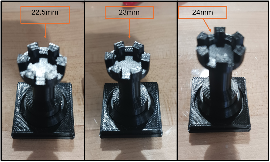
Several tolerancing concerns were solved with this initial test print. This included tolerancing of the cut-out in the tile in reference to the base size of the pieces. This tolerance can be seen in label 1 in Figure 12. The pieces have a base diameter of 22 mm. The cut-out had the desired effect of allowing easy moving of pieces during play but did not allow significant horizontal movement during transport. The cut-out diameter was varied from 22.5 mm, 23mm, and 24mm. This can be seen in Figure 13. This test helped determine the amount of clearance that allows easy removal during gameplay but not much horizontal movement during transportation. The 22.5 mm was a good fit that did not allow much horizontal movement of the piece but also was easy enough to move as if the piece was getting moved during a game. The 23mm and 24mm had too much movement with the base of the piece. These fits can be seen in Figure 14. As a result of this test, a cut out of 22.5 mm diameter was chosen for the next version of this board cutouts.

Another tolerancing concern was the fit between the board and the box. This tolerance can be seen in label 2 in Figure 12 as seen in the full-size CAD. The idea behind this was that the board would have little to no vertical movement during transportation. For this reason, a slot was cut into the box which would hold the board down during transportation but would allow the board to slide out easily. A test print validated this intent. A small single tile was printed into a smaller box but with the same clearances to test this idea. The results showed that there was a snug initial fit both due to a seam line present in the tile as well as some thermal warpage of the tile due to its thinner nature. However, with minor sanding and post-processing, the tile slides into and out of the box with minimal effort. This is demonstrated in Figure 15. With this in mind, the tolerancing had to take into account more thermal warpage or accept that post-processing has to occur for each board printed.

The final tolerancing question was to determine how to create a lid for the box. The initial plan was to use a size-on-size hole and pin to hold the box closed during transportation. This tolerance can be seen in label 3 of Figure 12. This tested the tolerancing limits on the FFF printer to determine if this was a viable option for the closing mechanism. The results of the test concluded that straight from the printer – the pin and hole system did not mesh due to a seam line on the pin. However, after minimal sanding and removal of this seam line, the lid snuggly fit into place but still allowed for easy removal when desired. This is demonstrated in Figure 16 below. With this in mind, the clearance was increased to account for this seam.

While working on the proper dimensions for the chess pieces, tile sizes, and other surrounding materials, it was a good idea to also test the Bambu Labs “Automatic Material Switcher” (AMS) that would be used to change the PLA color between black and white to create alternating chess tiles within the play area. This way, the base of the chess board and the chess tiles can all be made in one go conveniently, but on the other hand, this would make the total print time much longer. After confirming the 22.5 mm diameter circular pockets for the chess pieces to rest in Figure 13 and Figure 14, a 4×8 tile PLA plate was created for multiple tiles to sit on top of and create one solid body to test how the AMS switcher would behave and if it would give the intended results. Figure 17 below shows the result of the 4×8 test board with the AMS filament switcher in action, programmed from the Bambou Labs software. Each chess tile has a smaller size hole inside each of the larger holes, to also test for diameter required to press fit small circular magnets about 2 mm in diameter.

The result of this print was unexpected and is one that was decided to be too unprofessional looking for the board design. Gaps between each chess tile were created to allow for filament switching and coloring within the Bambu Labs software. But even then, the majority of black print had too much of an impact on the white tiles, and black color started bleeding through them. Plus, using the switcher requires an additional “prime tower zone” within the initial capable print volume of the printer (256 mm x 256 mm x 256mm), meaning the AMS would be unusable for larger prints. Knowing this, using the AMS switcher was removed from consideration for the board, necessitating a board redesign. Another possible solution would be the utilization of a dual nozzle 3d printer.
Initial Transforming Pawn Testing:
The first version of the prototype pawn piece was successfully printed and assembled. Because of the transformation mechanisms, many components consist of multiple critical dimensions. Due to the small size of the pawn piece and the sensitivity of some critical dimensions, the Bambu 3D printer did not execute some details nicely. Thus, many components required significant post-processing steps, such as sanding, to fit together. The printing results after assembling are shown below.


Figure 18: Printed pawn piece in its pawn form and rook form.
Initial Piece Testing:
Test prints of the king, bishop, knight, and rook were carried out to ensure the printability of the designs, including the resolution of the small features and viability of necessary support structures and the associated post-processing. An image of the bishop, king, and knight prints is shown below.

A print height of 0.16 mm was used, which produced smooth curves that were not too distracting under normal light conditions. The support structures for the knight were able to be completely removed without much hassle and left a clean finish. Small features such as the bishop’s button, king’s cross, and knight’s eye were all on the small side. The overall size of these features was increased for the redesigned pieces to prevent them from easily breaking off due to the thin geometry of these features.
Redesign Process
With the experience gained from the initial designs and working with the Bambu X1 Carbon, it was deemed best to go back to the drawing board to redesign the board and lid. The main goal during this redesign phase was to develop a product that was easy to print with minimal support and produce a professional, clean result. We wanted the end user to be able to send the files directly to the printer and assemble the least amount of parts possible. Small parts were merged and necessary post-processing was eliminated wherever possible.
Board Redesign
Deviating from the failed chess board prototype in Figure 16, the new board would instead be split into three parts: black chess tiles, white chess tiles, and a neutral-colored (gray) board base that all the tiles would snap onto. The magnets were initially designed to be housed in a space between the board base and each tile. Each tile then presses into the grayboard using two circular protrusions. Doing so in this order hides the magnets inside the tile body when fully assembled. An additional benefit of printing each tile separately was to have the textured PEI bed surface on the exposed side of the chessboard. A 4×4 trial print was made to test the tolerances, magnetic strength, and potential thermal warpage of this design. An image of this test print is shown in Figure 20 below.

After printing this test piece of the board, it was clear that the magnetic force between the pieces and the tiles was not strong enough. To fix this, the final board design has the magnet inlays incorporated entirely into the body of each tile and pressed into the bottom side of each tile. With this design, the distance between the two magnets went from 1.4 mm to 0.4 mm, significantly increasing the magnetic force between the tiles and the pieces.
Everything else about the test print worked as expected. Thermal warpage was insignificant, and all press fits were comfortable to achieve by hand. The press fit securely fixed the tiles to the board base with no chance of loosening with regular use. All the tiles were perfectly aligned on top of the board and gave the clean, professional look we were looking for.
Having made these changes, a full-scale board was then printed. This can be seen below in Figures 21 and 22.


Transformable Pawns Redesign
The first design and 3D print of the transformable pawn was largely a success. It was decided to continue forward with this design. The piece was able to be simplified from the original 5 parts down to 2 parts. This was done by removing the pin and making it part of the pawn head. This was possible without support because the pin was changed to only protrude from one side of the pawn head, rather than both sides. The shell was removed, as the friction between the pawn base and the pawn head was sufficient to keep it from falling down during play after adjusting the appropriate tolerances. The pawn body was also simplified from two separate pieces joining together to one cohesive piece which temporarily bends during assembly to accommodate the pawn heads. The initial and redesigned pawns can be seen in Figures 23 and 24, respectively.


Figure 23: Issues that occurred with the first design of the transformable pawn piece.

It was decided to include a total of 5 transformable pawns per color: two queens, a rook, a knight, and a bishop. The remaining 3 pawns were printed as solid pieces without any transforming mechanism but in the same shape as the transformable pawns.
Lid Redesign
The lid was originally designed to be a sliding cover. Due to the tricky tolerances and concerns regarding the printability of this design, it was decided to instead go with a traditional “over the top” lid design. Two lids were printed to test the clearance required to comfortably place and remove the lid from the board base while exploring the possibility of using this fit to help secure the lid to the board. To assist with this, inlays for magnets were created in all 4 corners of both the lid and board base. The idea to create supports in the lid to hold the pieces in place during transport was also experimented with. It was decided to print these supports as separate parts before printing them together with the lid, just in case the supports turned out to be unprintable. Evidence of this can be seen in the following figure as the ‘X’ inlays on the inside top surface of the cover.


Figure 25: First version of the lid.
The first trial print of the lid succeeded without any printer errors. The lid fits onto the board base, but there was more clearance than intended. This meant the lid shifted around slightly on the board. It was also observed that the strength provided by the four magnets was insufficient to keep the board base from falling out from beneath the lid when picking up the assembly by the lid. The experimental support prints turned out to be unprintable, as they were too tall and too thin to hold steady while printing the upper layers. Due to the significantly increased print time and cost of adding piece supports to the inside of the lid, the idea was scrapped. The magnetic attraction between the pieces and the board was decided to be adequate to keep the pieces in place during travel. With these learnings, the lid was redesigned and reprinted, as can be seen in Figure 26.

Piece Redesign


Figure 27: Final design of the pieces on the board.
All pieces received minor design adjustments for aesthetic improvement and structural integrity improvements. The minimum neck diameter of the pieces was increased and made consistent across all pieces. The knight’s neck size was also increased, leading to a better horse-shape resemblance than the original design. Additionally, the eye that was unnoticeably small on the original knight was increased and is now visible in the final design. The buttons on the queen and bishop were enlarged. The features of the queen’s crown were thickened to ensure its strength, as well as the king’s cross. The rook was redesigned to have a curved aesthetic, making it cohesive with the style of the other pieces. Finally, a dual-color feature was added to all pieces, including the pawns. This was done in a way that minimized the number of filament changes in the printing process. This ensured minimal waste of filament. This was accomplished by designing every piece to change color in the same z-coordinate range, ensuring that no filament changes were required from piece to piece on a single layer. A slight bleed-through was observed on the white pieces, and this was rectified in the finalized design by increasing the immediate thickness of the pieces after the final filament change. In addition, the layer height was reduced from 0.16 mm to 0.12 mm. This resulted in a smoother and slightly more matte finish.
Printing and Assembly
The entire board assembly requires 4 print beds to complete. Two for the white and black tiles and plates separately, one for the board base, and one for the board lid.
| Print Plate | Material (g) | Print time | Layer height (mm) | Infill (%) | Cost* ($) |
| Black tiles+pieces | 91.27 | 4h51m | 0.12 | 15 | 4.80 |
| White tiles+pieces | 91.27 | 4h51m | 0.12 | 15 | 4.80 |
| Board base | 156.77 | 4h10m | 0.20 | 10 | 7.78 |
| Lid | 246.08 | 5h37m | 0.20 | 10 | 11.43 |
| TOTAL | 585.39 | 19h29m | N/A | N/A | 28.81 |
*Cost is estimated according to the UW Madison Makerspace.

The assembly process was straightforward and relatively easy, but time-consuming, as there are 104 magnets to press fit into the tiles and pieces. However, little to no post-processing was required, all of which was entirely due to small printing defects. This helped make the process as enjoyable as possible. The magnets chosen were 2×5 mm circular magnets purchased from Amazon for about $6. This brought the cost of one set to $33.81.
Conclusion and Future Work
Ultimately, the desire to make a portable chessboard with FFF methods was accomplished. The pieces as well as the board fit aesthetically together. The eventual use of magnets allows for travel from one location to another while also keeping the game saved. However, there are still additional items that could be added or changed to improve the look of the board. For example, experimentation with SLA would allow better surface finishes on the pieces but could increase the cost of printing. Moreover, the magnets are visible through the tiles, in which changing the material might prevent this seeing of the magnets. However, with the time allotted for this class, the final product was an aesthetically pleasing and highly functional chess board that could be moved easily.