Project Overview
Framing a poster can be expensive and can add a lot of weight. This excess weight can make large nails a necessity to hang up any posters in a dorm or apartment, which are far more difficult to repair due to a larger hole, as well as the need for a hammer or other tools. Solutions such as thumb tacks and adhesive putty can cause damage to the poster itself. For this reason, we are looking to make a poster hanging system that is a cheaper alternative to frames, while still not damaging the poster like a thumb tack would. Our initial concept is a device that attaches to the corners of posters via press fit, which has a tack sticking out of it to be attached to the wall.
Initial design
We wanted to observe the feasibility of printing a paper thin gap and tack so we sought out to print the proposed design for our poster clamp idea. This print was done using an Ultimaker S5, and it took two hours and 46 minutes to print. PLA in combination with PVA, a water soluble support, were used to make the part. Two orientations were tested to see which could print the gap and tack better. Figure 1 displays the finished parts in the two orientations.
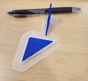 Figure 1: Poster clamp initial design, printed in PLA with PVA supports.
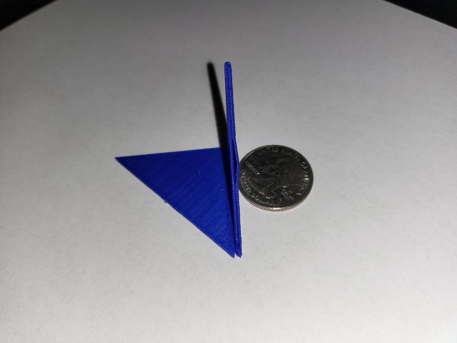
Unfortunately, both orientations produced less than desirable results, with the gaps being fused together, and the tacks being too small to the point where they broke when a slight pressure was applied. The fused gap can be observed in Figure 2, shown below.
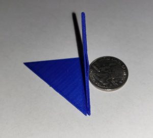 Figure 2: Side profile of poster clamp initial design.
With a fused gap, paper is not able to be slipped into the poster clamp so this kind of design was deemed infeasible for a 3D printing application. Furthermore, tack redesign is required to properly secure the poster clamp to the wall. A positive take away from the initial design is the appropriate size of the poster clamp itself. We intend to keep the poster clamp length and width the same for subsequent designs.
Redesign
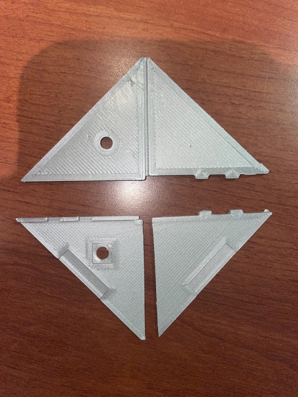
Our team has gone through a few different design iterations to solve the various issues that have arisen from our initial design. To solve the issue of the gap fusing together and not leaving enough space for a poster, we decided to incorporate a living hinge into our design. This hinge can be seen in Figures 3 and 4.
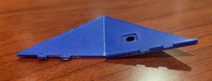 Figure 3: Poster clamp redesign with live hinge and interlocking tabs (open).
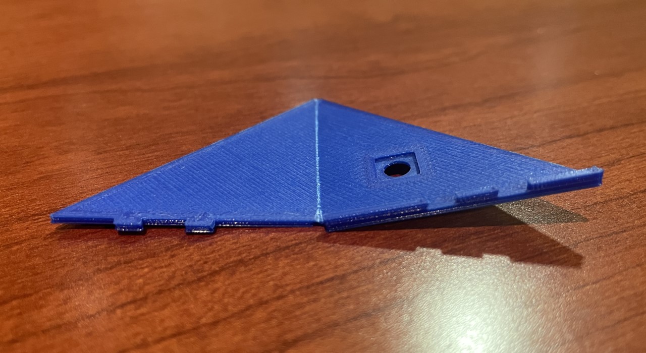
With this design, we ensured that only one printed piece is necessary, which makes it faster to manufacture and simpler to install. A living hinge is made possible by simply placing significantly less material at the hinge location.
The hinge is closed by interlocking four tabs shown on the longest side of the poster clamp. These tabs can be seen both in Figures 3 and 4.
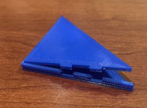 Figure 4: Poster clamp redesign with living hinge and interlocking tabs (closed).
These proved more challenging than we had anticipated since they did not align when the hinge was bent closed. We reprinted, adjusting their location but still had only two of the four tabs properly engaged. This problem primarily stems from where the part bends in the live hinge not being the direct center of the thin material.
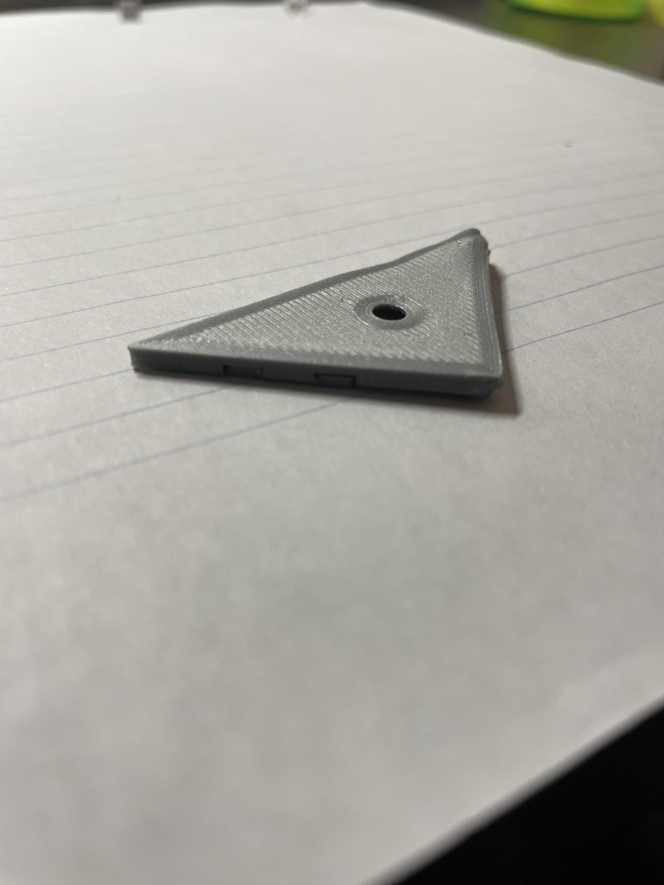
A removable tack was added on the back to allow for many different sized tacks to be printed and tested. The hole for these tack inserts can be seen in Figure 3. A number of tacks of various sizes and angles were printed to see how they would compare in terms of damage they cause and ease of installation.
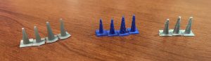 Figure 5: Three different print sets of tack design.
The leftmost is the SLA tack, and the middle and rightmost sets are FFF tacks printed at different times. Printing the removable tack was originally an idea for easier testing and prototyping, but there are benefits to being able to remove the tack. The primary benefit is that the customer has the ability to choose how they want their poster mounted. With a removable tack, they can choose to use adhesive such as Command Strips as the main method to attach the poster clamp to the wall. This would allow for the poster to remain undamaged and allow for use in buildings that do not use drywall, such as cement block or brick walls.
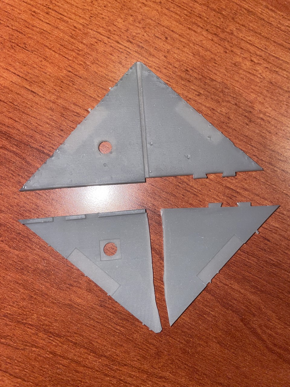
We had originally planned on testing two materials, ABS and PLA, to determine which would be better for our application, but due to ABS unavailability, we instead chose to compare two processes: SLA and FFF. FFF is far cheaper and takes less time, along with being more pliable after post processing which we address more in the testing section. SLA has a better surface finish but that is really the only positive, and so moving forward, we are going to continue using FFF. The two prints can be seen side by side in Figure 6. The only part that we are considering using SLA for is the removable tacks as they are strong and the smoother finish may be less damaging, but further testing is needed to confirm this.
A further redesign implemented a recessed area to both sides of the live hinge. This allows the two halves to be easily separated when they snuggly fit together. A faint lighter gray box can be seen in the bottom picture of Figure 6, highlighting the recessed area.
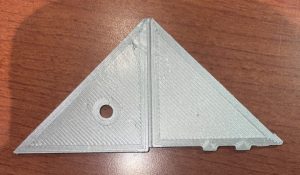
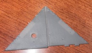 Figure 6: Further redesigned poster clamp with FFF (top), printed with SLA (bottom).
Testing
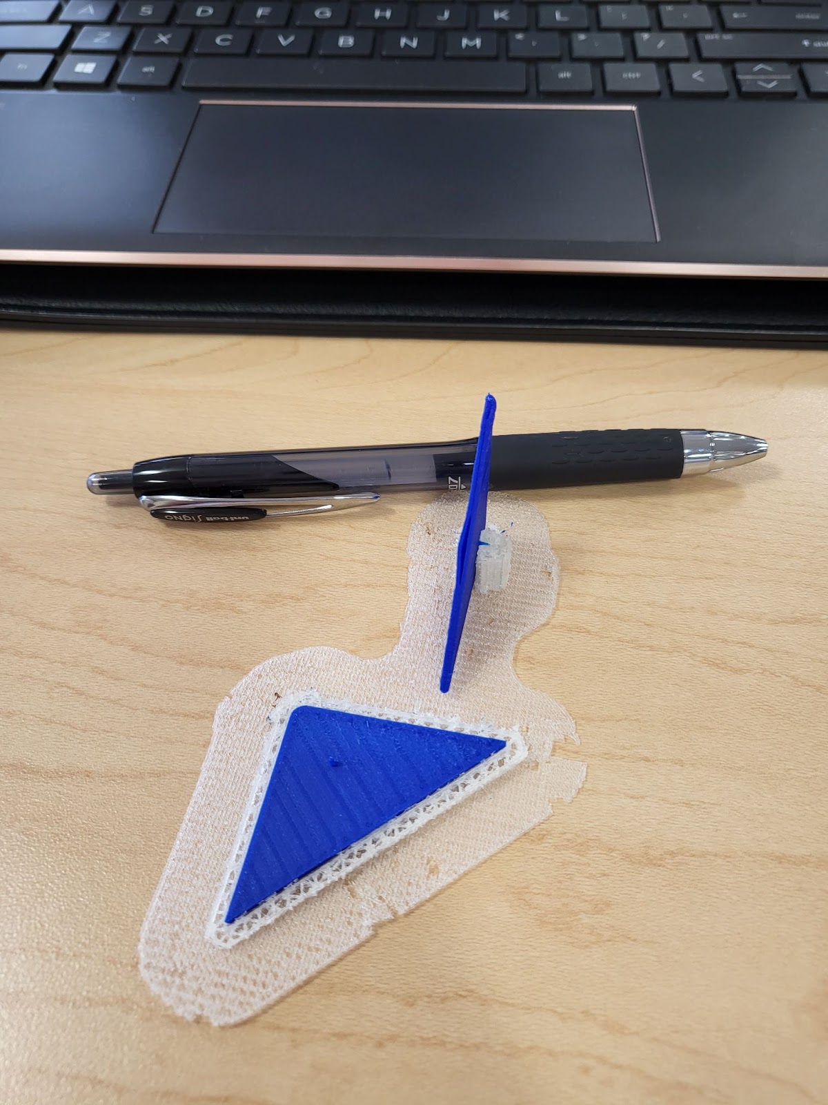
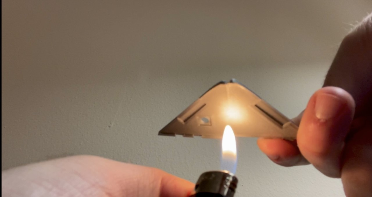
We noticed that there was a tendency for the part to snap in half at the live hinge interface upon initially bending it. In order to counteract this, Hubs, a 3D printing prototyping company, recommends two things [1]. One is to orient the part in a way that the central axis of the hinge is parallel to the Z-axis. This ensures that the live hinge is printed layer by layer, leading to less frequent brittle failure. The other recommendation is to anneal the live hinge surface before initially setting the bend. This can be done by simply raising the temperature at the live hinge interface and immediately bending the part when the material strength is significantly reduced, thus eliminating the possibility for a brittle failure. Figure 7 displays the annealing process on one of the FFF poster clamp testing specimens.
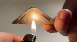 Figure 7: Annealing process done to one of the FFF poster clamp test specimens.
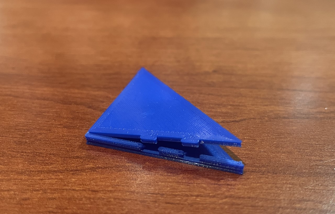
The result of annealing the FFF test specimen was that it did not break in half as others in the past did. Additionally, we were able to manipulate where the live hinge creases, and consequently, we were able to line up the interlocking tabs very easily. The annealed part is shown in Figure 8. The PLA material is a thermoplastic which means reheating it can cause it to be more malleable while retaining its molecular structure. Conversely, the SLA test specimen broke in half just the same as if it were unaffected. This makes sense because the resin used in the SLA process is a thermoset that requires UV curing to solidify. Heating is not a part of the process, and as a result, applying heat to the material does not make it more malleable and instead creates a weaker joint.
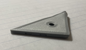 Figure 8: Annealed FFF poster clamp with functional locking mechanism.
With our refined design, we wished to conduct a fatigue test. Our fatigue experiment consisted of comparing the survivability of an unaffected poster clamp to an annealed one. In order to bring a product like this to market, it was determined that the live hinge should have a lifespan of one hundred cycles in which a cycle consists of one open and one close of the poster clamp. This quantity of one hundred cycles far exceeds the estimated usage in a realistic application. Realistically, the poster clamp will be opened and closed a maximum of ten times in its lifetime. For this reason, we agreed on a fatigue safety factor of ten to account for potential variation in printing quality if this product is manufactured on a larger scale.
The results showed that both the unaffected specimen and the annealed specimen passed with each still possessing the ability to open and close in one piece after one hundred cycles. This suggests that annealing does not affect the live hinge’s structural integrity once it has cooled. On a larger scale, additional consideration will be given to the feasibility of annealing and setting the bend on all parts.
Further testing surrounding the ability for the poster clamp to securely hold a piece of poster paper for an extended period of time is desired. This is an important test because the primary design specification of this project is for our product to be able to hold a poster. We believe that additional redesign using the information we learned from our initial test will greatly improve the credibility of the conclusions made from this final test.
Going Forward
We have identified some aspects of our design that could be iterated on for our next print. We would like to try printing using FFF with nylon as the material, which was recommended by Hubs [1]. They have stated that this is the best material for a live hinge in a one-material FFF part. We are hoping that using nylon will make annealing the hinge unnecessary, which would be very desirable if this were to be mass produced. We also plan to add filets to the live hinge, and orient the central axis of the hinge along the Z-axis. If the live hinge is still giving us problems after these changes, we will consider a redesign.
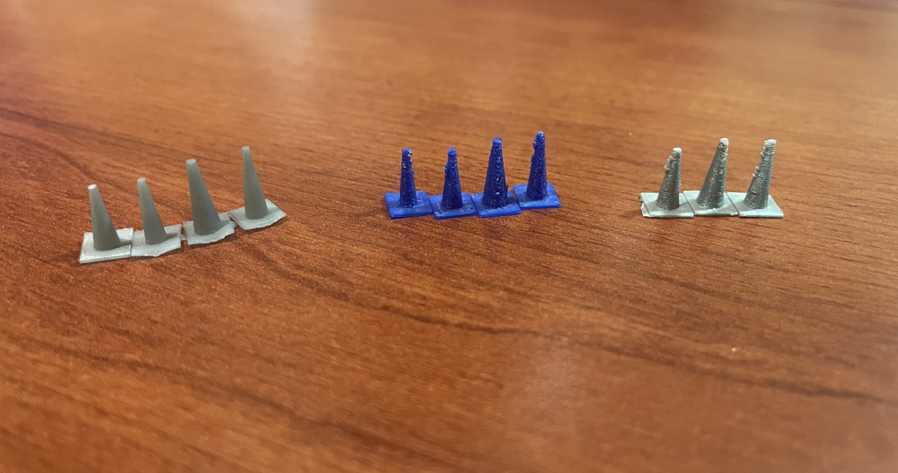
The current tack design also needs to be reconsidered. The 3D printed tracks presented some difficulties when attempting to install them for testing purposes. Holes had to be punched in the wall before installation, as the tacks are not sharp or strong enough to easily puncture the drywall. The tacks also left holes that were larger than desired. A comparison of the holes can be seen in Figure 9.
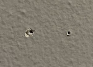 Figure 9: Hole left from 3D printed tack (left), hole left from conventional metal tack (right).
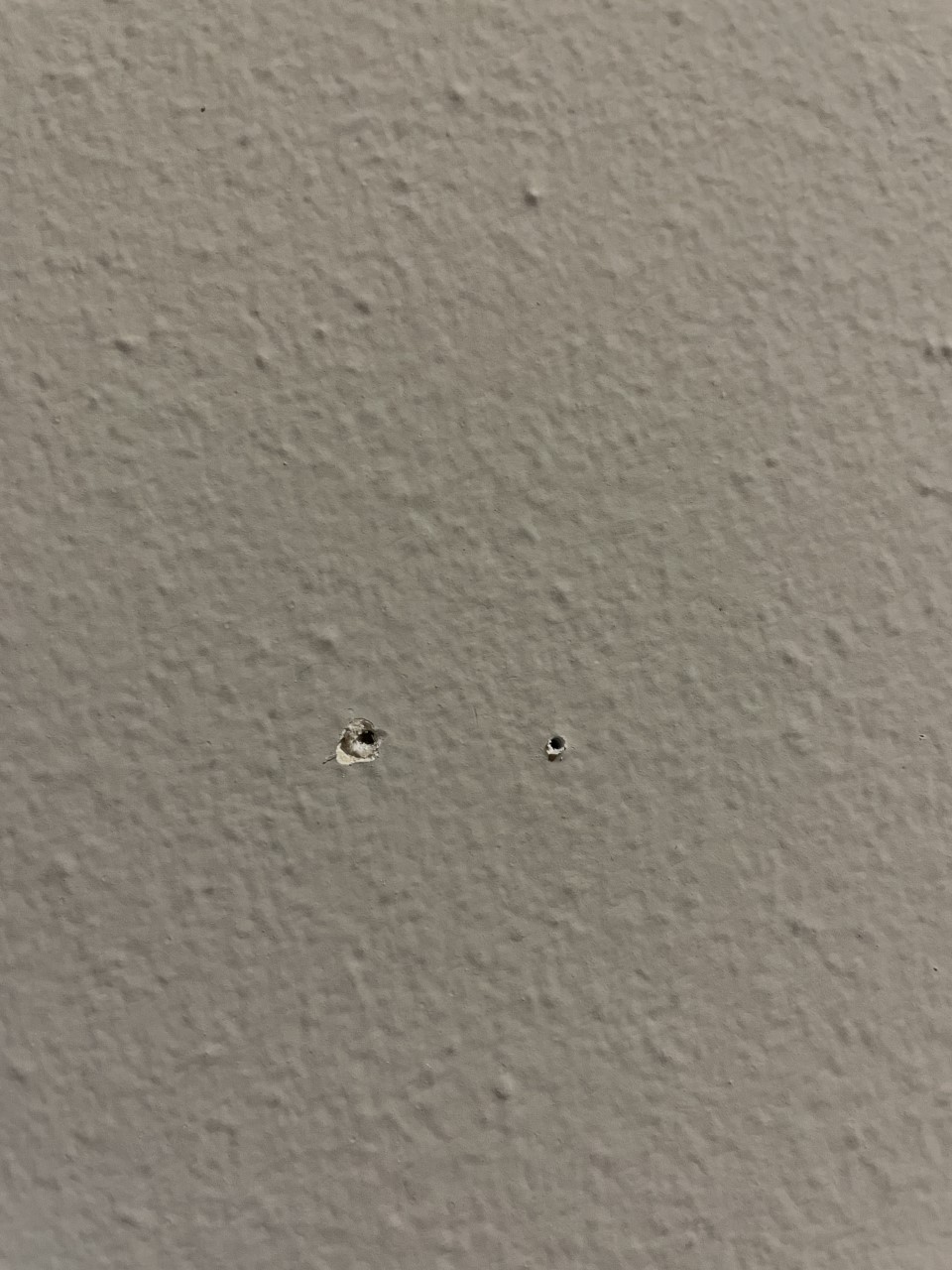
We believe the best idea to fix this is to make the clamp compatible with flat metal tacks that can be purchased separately. While we may run more tests with the 3D printed tacks, we will pivot away from that idea if difficulties persist.
Testing going forward will revolve around the ability of the clamp to firmly hold a poster for a significant amount of time without causing any damage to the poster. Tests will be run with the FFF PLA clamp, along with the FFF nylon clamp if that design successfully passes the fatigue test previously conducted on the PLA clamp. Paper will be clamped and tacked to a wall, where it will sit for one week. We will hang multiple papers at a time, with different weights attached to them. Paper clips will be added to the paper to increase the weight and simulate the weight of a thicker poster paper. After the week has passed, the paper and clamp will be inspected to determine if the paper has moved, or if the clamp has damaged the paper. This will be done by taking pictures of the paper and clamp before and after the week long test. Measurements will also be taken before and after to quantify the movement of the paper. Ease of installation will be documented during these tests, which will factor into the decision for changing the tack design. Results for these tests will drive our decision making for future iterations of our design.
We have been advised to research current patents that could be similar to our design. This research will be conducted soon, and information surrounding this research will be included in our final report.