Project Overview
To be compatible with granular materials in additive manufacturing, a screw-based extrusion 3D printer was created. However, the pain point of producing any model with this 3D printer is the discontinuous feeding due to particle clogging issues in the feeding zone. The purpose of this project is to improve the performance of the feed zone of a single screw extrusion printer and avoid print failures due to discontinuous extrusion. The first two assumptions are the surface finish of the FFF-printed throat and that the throat is not designed for particles with sharp shapes. During the experiment, the real cause of blocking was found, and some feasible solutions were proposed.
The process outlined in the proposal, shown in Figure 1, was followed to test the original throat design printed using SLA. The SLA material was smoother and thought to be better for preventing clogs. The part was tested and found that material still was clumped together. The material in the throat and the extrusion system was analyzed to determine the issue. A new method to solve the problem is outlined in the following sections.
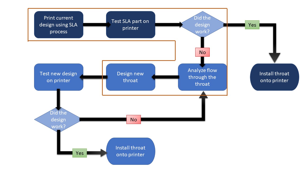
Figure 1. Original process outline and current steps.
Blocking Reason
From the literature review, the types of blockages in hopper/funnel systems are mainly divided into two types, namely ratholing and bridging, as shown in Figure 2a. The throat was removed from the printing head in order to investigate if either of these phenomena were to blame for the blockage, however, pouring pellets through the throat when disconnected revealed no signs of either phenomena. An alternative hypothesis for throat blockage was that the pellets were sticking together in a near-melt condition due to elevated temperatures. A sample of pellets was placed in temperature conditions similar to those in the throat region. Upon removal, the pellets in the sample had fused, indicating that the primary reason for blockage was the pellets fusing together. The printer was run with pellets in typical operating conditions and the feeder was removed to reveal a mass of fused pellets at the feeding zone seen in Figure 2b. This confirmed that the blockage was attributed to elevated material cohesiveness which is most reminiscent of the ratholing phenomenon.
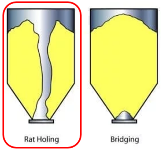
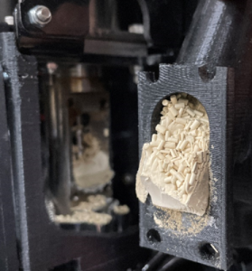
Figure 2. a) Schematics of Two Types of Blockage; b) The Blockage State on Botero’s Throat.
The pellets should be melting within the screw extruder, not in the feeder throat itself. This causes the pellets to get stuck together and coagulate into one mass, stopping the flow of material to the extruder. There is no cooling around the throat or the top of the extruder, which causes the pellets to be melted. In a normal screw extruder, there would be a cooling jacket around the feeder, and then heaters as the material goes through the screw extruder, as shown in Figure 3.

Figure 3. Single Screw Extruder at Melting Section [1].
In order to observe the pellets performance in the feeding zone, the throat printed by clear resin was installed on the printing head after the sanding, as shown in Figure 4.
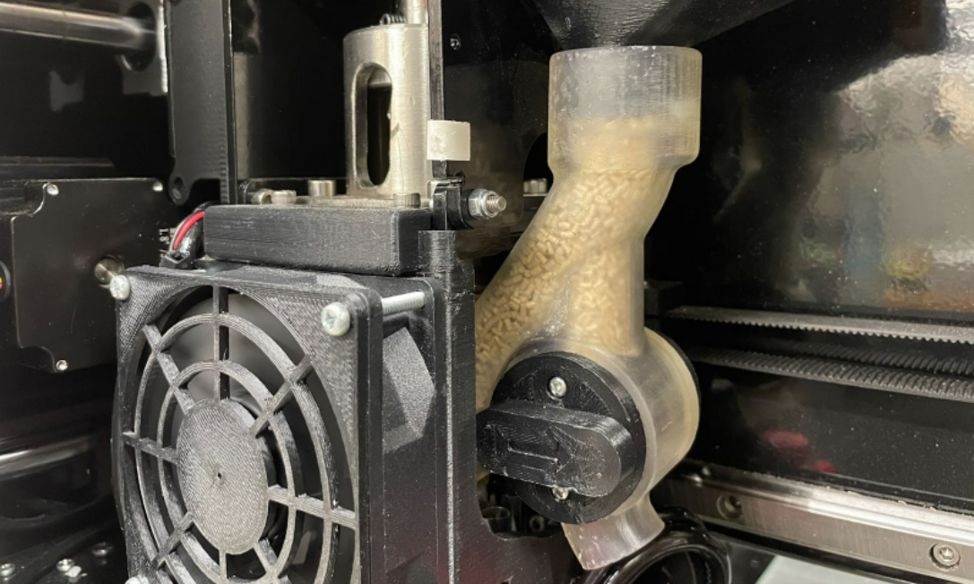
Figure 4. Installation of the Throat Printed from Clear Resin.
Problem-solving
1. Adjust temperature profile
The material that we are using is ABS/BiTiO3 composites with 5% plasticizer by weight. The result of TGA shows that the glass transition temperature (Tg) of the composites is lower than the room temperature [2]. As the feeding zone requires the material to be still in pellet-form, the temperature should be lower than Tg. Therefore, the original temperature profile,as shown in Figure 5a, is high enough to make the pellets deformed. The most direct way to solve this issue is decreasing the temperature at zone 1 to 0? and zone 2 to 120?, as shown in Figure 5b. However, zone 2 is close to zone 3, where the temperature at zone 3 is still around 40?, no matter how low the target temperature was set up, so designing a cooling system is necessary. The other problem is the clutching issue. If the temperature of zone 2 is lower than 120?, the materials would be solidified in zone 2.
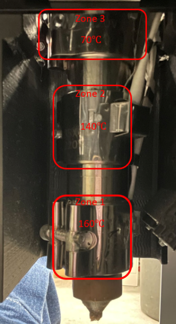
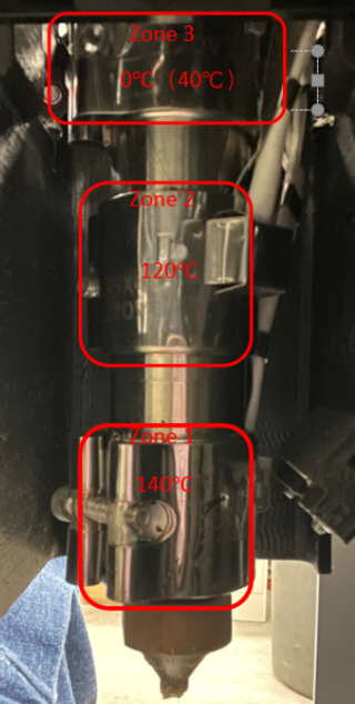
Figure 5. a) The original temperature profile was set at different heating zones; b) The improved temperature profile for solving the early-melting issue.
2. Design a cooling system
Addressing the elevated temperature at Zone 1 is critical to preventing the pellet-form material from sticking to itself and forming a clogging mass. As previously mentioned, cooling the entry point of screw extruder systems is commonly achieved with a cooling jacket. Given the tight geometry at the screw entry point, integrating an effective cooling jacket would likely require design changes to the existing components surrounding the throat. The updated heating zone temperatures indicated in Figure 5b may reduce the entry point temperature enough to alleviate the issue without a cooling jacket. Further testing is required to verify this.
If the zone temperature changes prove ineffective, an alternative cooling system is under development which may resolve the clogging issue. The main pellet supply for the printer utilizes a compressed air system to maintain consistent flow in the pellet hopper. A second hose could branch off of the air supply and serve a similar function at the screw entry point. This could place cold air directly into the hottest part of the throat and jostle the pellets within the throat to further prevent sticking. Figure 6 shows a diagram of the proposed solution.
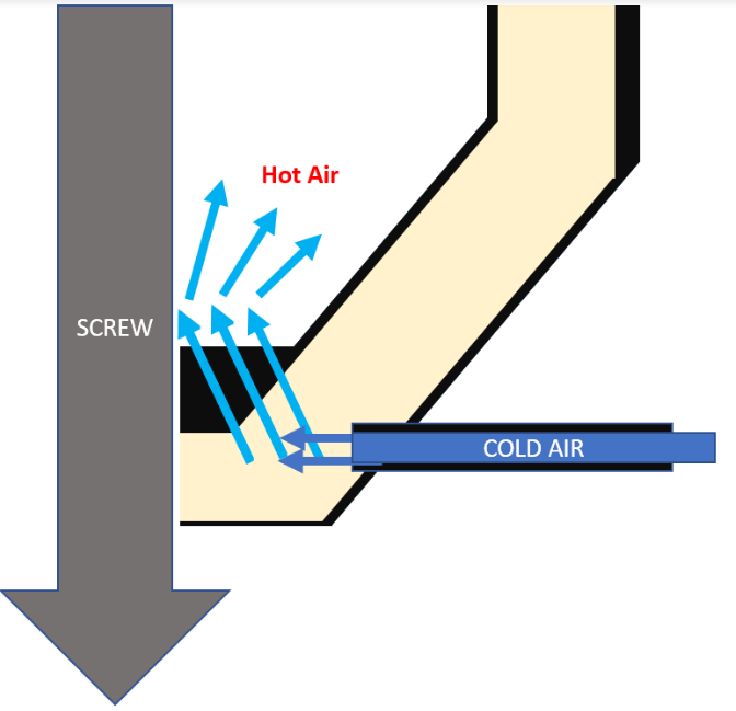
Figure 6. Proposed air-cooling system
Leveraging 3D printing allows for controlled air flow through the walls and interior of the throat and for the hose attachment point to be shifted back away from the screw where there is ample space to avoid extruder hardware.
A simpler potential solution would be to adjust the throat aperture to be narrower than the distance between two flights of the extruder screw. If the fused mass constantly presses against the outer walls of one or more screw flights, it may be impeded by the screw acting as a variable wall and the mass having too slow a flow rate to enter the screw appreciably. Reducing the entry point diameter would allow the mass to increase the amount of time where no part of the screw resists it and where it can flow freely into the screw flutes. This may further restrict pellet flow due to bridging and/or ratholing in a reduced diameter channel, but it may be a viable solution if these phenomena are limited.
Conclusion
The initial reprint of the throat did not solve the issue but did provide some insights into what the real problem was. Analyzing the flow of the pellets and their properties showed that the reason for the clumping was that they were melting in the throat. Two methods are being pursued to solve this issue. The first method is adjusting the temperatures of the heating zones. Tests will be performed to determine how low the temperature can be without preventing melting within the screw. The second method to further lower the temperature of the pellets without compromising the melting in the screw is to implement a cooling system. The cooling system would use compressed air that is already supplied to the screw and split it to also cool the pellets. Further testing will be performed to test both solution methods and determine if more design is needed. This process is outlined in the flowchart in Figure 7.
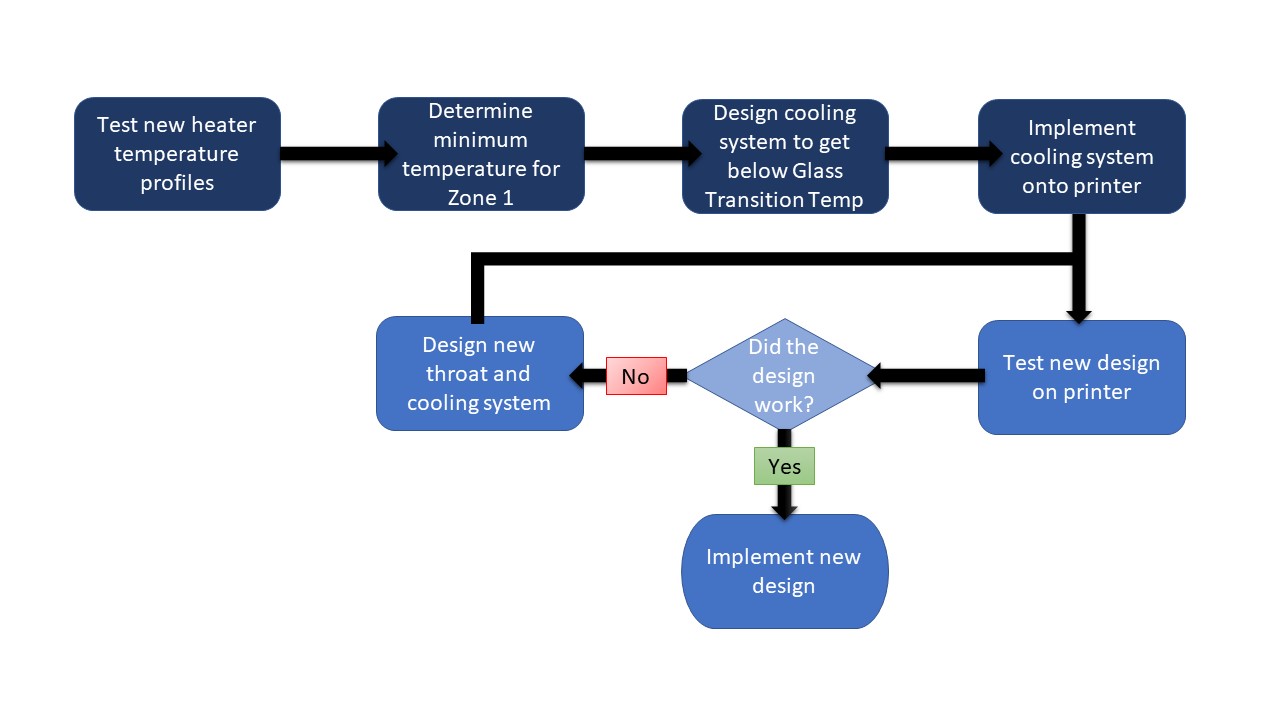
Figure 7. Process for testing two solution methods.
References
- Understanding Polymer Processing. 2nd Edition. Tim A. Osswald, 2017.
- G. A. Mazzei Capote, M. C. Montoya-Ospina, Z. Liu, M. S. Mattei, B. Liu, A. P. Delgado, Z. Yu, R. H. Goldsmith, and T. A. Osswald, “Compounding a high-permittivity thermoplastic material and its applicability in manufacturing of microwave photonic crystals,” MDPI, 28-Mar-2022. [Online]. Available: https://www.mdpi.com/1996-1944/15/7/2492/html. [Accessed: 06-Apr-2022].