Low-Cost Star Tracker Using Additive Manufacturing
Tevis Linser and Ethan Burton, ME 514, University of Wisconsin-Madison
Abstract
Star trackers are mechanical devices that enable long-exposure astrophotography by compensating for the Earth’s rotation, allowing cameras to remain aligned with celestial objects over time. This paper presents the design, fabrication, and iterative development of a low-cost, barn door–style star tracker leveraging additive manufacturing techniques. The design utilizes an isosceles hinge mechanism actuated by a stepper motor and controlled via an Arduino microcontroller to achieve precise rotational tracking. Additive manufacturing was employed throughout the design process to produce lightweight, customizable components and to enable rapid prototyping. Early prototypes were printed using PLA filament on Fused Deposition Modeling (FDM) machines, allowing for low-cost validation of mechanical geometry and motor integration. Subsequent iterations target Stereolithography (SLA) or Selective Laser Sintering (SLS) processes to achieve tighter tolerances, reduce dimensional inaccuracies, and improve overall part robustness. To further enhance efficiency and minimize material usage, future versions will incorporate topology-optimized geometries enabled by the design freedom of additive processes. The final system demonstrates a functional, accessible, and customizable star tracker design, with plans for open-source release including CAD files, circuit diagrams, build instructions, and sample results. This work highlights the potential of additive manufacturing to enable precision instrumentation in amateur astronomy and educational settings.
Introduction
Astrophotography has grown rapidly in popularity among hobbyists and amateur astronomers, driven by the increasing accessibility of consumer-grade telescopes and digital cameras. One critical tool in long-exposure astrophotography is a star tracker which is a device that compensates for Earth’s rotation by gradually rotating a mounted camera to keep celestial objects in the same position relative to the sensor. This prevents star trails and allows for sharper, clearer images during prolonged exposures.
Despite their utility, commercial star trackers remain cost-prohibitive for many aspiring astrophotographers. Entry-level models typically range from $300 to over $1000 USD [1], placing them out of reach for students, educators, and hobbyists on a budget. This cost barrier limits access to high-quality astrophotography and excludes many from meaningful participation in space observation. Moreover, commercial trackers are often built with proprietary components and limited customization, reducing their adaptability to different user needs.
The global astrophotography accessories market is projected to grow from USD 265 million in 2024 to over USD 385 million by 2029, driven by increasing interest in astronomy education and space exploration [2]. Within this market, star trackers represent a significant niche with high margins and little innovation in cost-effective manufacturing methods. As 3D printing technologies mature, they offer a unique opportunity to reduce the cost and increase the accessibility of precision tracking devices through distributed, customizable fabrication.
An important factor is simple construction for hobbyist users, therefore, this work will focus on a barn door star tracker. A barn door star tracker consists of two hinged plates with one being fixed and the other allowed to move. This movement is accomplished by a threaded rod connecting the two plates, driven by a low-RPM motor which gradually opens the “barn door”. By aligning the hinge with the celestial pole (Polaris), as the hinge opens the Earth’s rotation is counteracted. This allows for long exposure photography without star trails.
Previous DIY barn door star tracker solutions offer some cost savings, but are generally limited in accuracy and mechanical performance due to their simple construction. Typical DIY barn door trackers are manufactured from wood and key dimensions are manufactured by hand by the user, leading to manufacturing error. This manufacturing error leads to poor quality trackers and turns hobbyists away from the hobby. Other open-source efforts like the OpenAstroTracker have shown that high-quality tracking is achievable at lower costs, but they often require CNC machining or high-end 3D printers that are not universally available [3].
This research project aims to design, fabricate, and test a fully functional barn door star tracker using polymer-based additive manufacturing processes, specifically FDM and SLA printing. By leveraging the precision of resin-based printing and the strength and affordability of filament-based methods, this project seeks to demonstrate that multi-process 3D printing can enable affordable, modular, and accessible tools for astrophotography. Our design emphasizes simplicity, mechanical reliability, and educational value, making it ideal for makers, students, and amateur astronomers who want to engage with the night sky through modern digital tools.
Design and Methods
To design the star tracker, first the kinematic relations to govern the angular motion needed to be developed. The device has to rotate at the same rate as the Earth’s angular velocity. This value is known as the sidereal rate and can be approximated by equation 1. The goal of these calculations is to determine the length between the hinge and the threaded rod location to produce the smallest tracking error, using a one RPM motor.
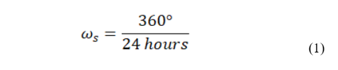
Where omega_s is defined by the Earth completing 1 full rotation (360 degrees) in 24 hours. Additionally, the lift produced by the stepper motor needs to be found to solve for the angular velocity of the star tracker. The lift produced by the motor can be calculated by equation 2, and the angular velocity of the actual star tracker can be calculated using equation 3.
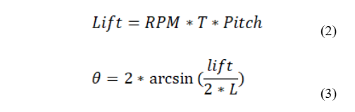
Where lift is the distance the “barn door” opens per exposure length, RPM is the set motor RPM, T is the desired camera exposure length, and pitch is the pitch of the thread used (M5). For equation 3, theta is the increase in the barn door angle relative to the base, and L is the length between the hinge and the threaded rod location. Finally, normalizing the ideal tracking rate with the exposure length, and the error between the ideal tracking rate and the tracking rate using these geometries can be seen in equation 4 and 5.
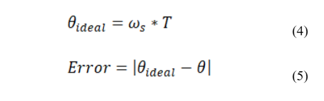
Where theta ideal is the ideal angle change through as a function of the camera exposure time. Lastly, error is the difference between the ideal and theoretical angle change. Solving these equations, using a one RPM motor and a M5 threaded rod for a thirty second exposure length, the smallest tracking error occurs at a length of 7.201 inches. The resulting error (converted to arc-seconds) was found to be less than 10 arc-seconds, which is less than an accepted rate of 50 arc-seconds for commercial solutions.
Electronics and Control
For the electronics and control, a NEMA 17 0.9 degree stepper motor was used in combination with a TMC2209 stepper motor driver. The TMC2209 allows for “microstepping” functionality allowing for even finer resolution rotating the stepper, although due to time constraints the microstepping function was not implemented. The controller used for the tracker is an Arduino Uno R3.
Design
To design the tracker, OnShape was used as the 3D modeling software. In total, six custom parts were designed to come together to make a fully operational star tracker. These parts include the fixed and moving base, both rotational threaded rod fixtures and holders, and a five watt laser mount. The final completed assembly can be seen below in Figure 1. Note: not shown in the assembly are the purchased components, which are a simple door hinge, stepper motor and electronics, and camera ball mount.
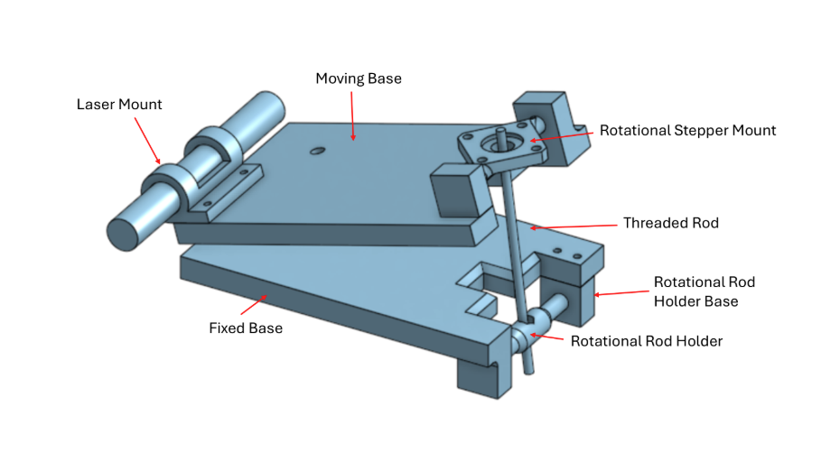
Figure 1. Complete CAD assembly of star tracker.
The design of the star tracker leverages the use of metal mechanical parts to provide strength to otherwise weak parts. All bolt holes on the tracker use heat set inserts to obtain a high quality reusable thread. The design uses primarily M4 bolts to attach the rod holder base as well as the laser mount. M5 bolts and inserts were used to attach the door hinge. A ¼ -20 insert and bolt are used to attach the camera ball mount. Lastly, M3 inserts and bolts were used to fix the stepper motor to the stepper base.
The laser on the tracker is used to celestially align the tracker. This is done by shining the laser directly at Polaris in the Northern Hemisphere. This aligns the tracker on the same “coordinate” system as the stars allowing for proper tracking. From there, the camera ball mount is then used to point the camera at whatever object the user is trying to photograph in the night sky.
An M5 bolt was used in the rotational rod holder attached to the fix base to be the base of where the threaded rod spins to achieve the angular change. The other end of the threaded rod is fixed to the output of the stepper motor. By turning the stepper motor counter-clockwise the tracker opens, achieving star tracking.
Iteration
The advantage of 3D printing means that multiple iterations can be rapidly produced to quickly arrive at the final product. Throughout the design process, multiple iterations were made for each of the parts. The iterations were used for improving tolerances, intitail oversights, and rigidity. The first iteration can be seen in Figure 2, where the first print of the star tracker was partially assembled. Upon assembly, it was realized that the tracker had issues with interference. This interference can be seen in Figure 3.
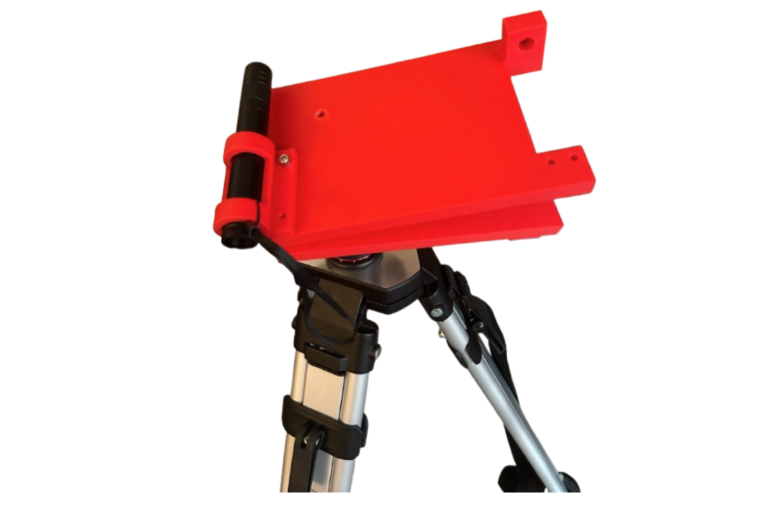
Figure 2. First print of the star tracker
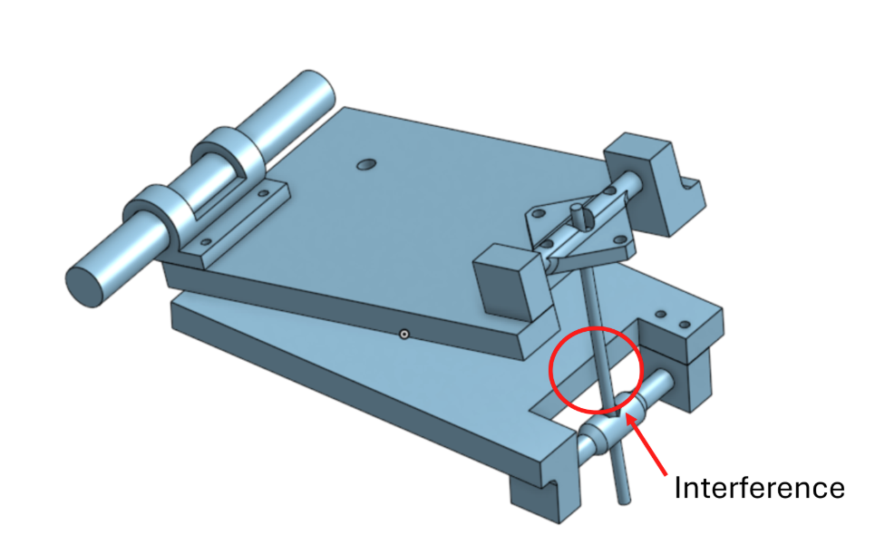
Figure 3. CAD model of the first iteration highlighting the interference between the fixed base and threaded rod.
In addition to the complete overall assembly, smaller test prints were also completed to test fits and insure proper clearances for interacting parts. Figure 4 shows an example test print where the rotational rod holder and base were printed as small parts to test fits between the two interacting parts. Additionally the sizing of the M5 nut and heat set inserts for the base were also tested.
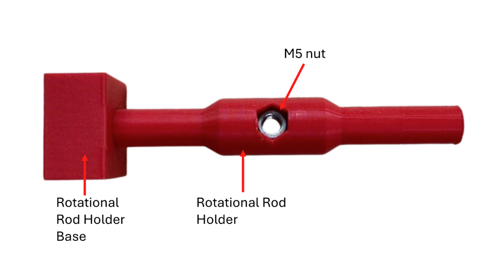
Figure 4. Test print to find tolerances and clearances for the parts used in the assembly.
Results
After a couple of iterations, the final tolerances and clearances were determined and input into the final CAD model. The current complete assembly with the camera attached can be seen in Figure 5. The final result of this work produced a fully functional star tracker that could be made using standard FDM 3D printing.
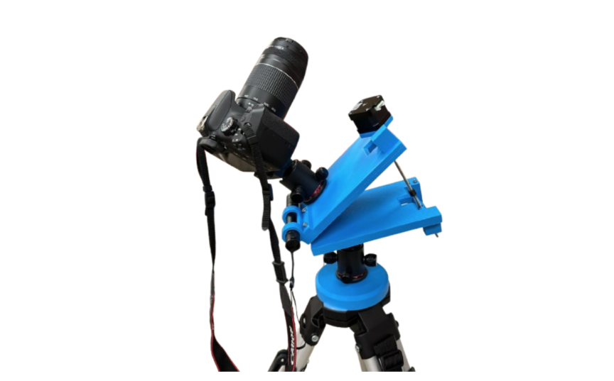
Figure 5. Complete star tracker assembly
Unfortunately at the time of writing, testing has yet to occur to find the tracking error of the developed tracker. However, it is worth noting that the current version of the tracker still has room for improvement. Due to tolerance stack up, and issues with rigidity, caused poor stepper motor performance due to slight misalignment. This will probably cause tracking error for longer exposure shots, but testing has not occurred to verify this claim.
Future Work
Future iterations of our star tracker project will focus on enhancing mechanical precision, optimizing material usage, and broadening accessibility through open-source dissemination.
One of the key challenges encountered in the current prototype was dimensional inaccuracy caused by cumulative tolerance stack-up in mechanically interfacing components. These tolerances, particularly prevalent in FDM-printed parts, resulted in slight misalignments with the motor mount resulting in poor motor function. To address this, future versions of the device will incorporate resin-based stereolithography (SLA) printing for high-precision subassemblies. SLA printing offers significantly tighter dimensional tolerances and finer feature resolution compared to FDM, enabling more reliable mechanical mating and reducing the need for post-processing or iterative rework. This is particularly important in the rotational surfaces that directly affect rotational smoothness and stepper motor performance.
In tandem with improved fabrication techniques, we are exploring the use of topology optimization algorithms to redesign structural components for reduced material consumption without compromising stiffness or load-bearing capacity. These algorithms can leverage the complex geometries enabled by additive manufacturing, allowing us to significantly reduce part weight and print time, while maintaining high accuracy parts. This will be especially beneficial when utilizing more costly printing processes like SLA, where minimizing resin volume directly lowers production cost.
To maximize the educational and community value of our work, we intend to release the final design as an open-source hardware project. This release will include: full 3D CAD models in native and exchange formats, STL files optimized for FDM and SLA printing, electrical schematics, and software code for motor control and user interface, detailed build instructions and bill of materials (BOM), and example images taken with the device to demonstrate functionality.
The open-source approach will not only encourage replication and customization by hobbyists and students but also invite contributions from a global community of engineers and makers. By documenting our design and lessons learned, we aim to lower the barrier to entry for advanced DIY astrophotography and encourage broader exploration into the intersection of precision optics and consumer-grade additive manufacturing.
Discussion and Impact
This project demonstrates how additive manufacturing (AM) can be leveraged to develop a precise, functional, and low-cost star tracker. By applying polymer-based 3D printing to the design and fabrication of a barn door–style tracker, we validated the feasibility of using AM for functional motion-control systems typically constrained by tight tolerances and complex geometries.
A primary finding of this work was the importance of matching 3D printing technologies to part performance requirements. Initial prototypes fabricated with FDM proved ideal for rapid design iteration, but introduced variability in dimensional accuracy that led to tolerance stack-up errors in mechanical assemblies. These errors adversely affected alignment in critical components reducing tracking performance. In response, the project’s later stages shifted toward the prospect of SLA, which would offer greater precision and surface quality. This proposed transition illustrates the critical tradeoff between prototyping speed and manufacturing accuracy in AM-based mechanical systems.
Beyond its technical outcomes, the project highlights the broader impact of increasing access to precision instruments through additive manufacturing. By making the final design open-source, including CAD files, circuit diagrams, and instructions, the star tracker becomes a tool not only for amateur astronomers, but also for students, educators, and hobbyists exploring motion systems, embedded control, and iterative design. This project demonstrates how additive manufacturing can significantly lower barriers to hands-on engineering and scientific experimentation, encouraging innovation outside of traditional industry environments.
Conclusions
This project successfully demonstrates the potential of additive manufacturing for creating a low-cost, customizable star tracker capable of precise astronomical tracking. Through iterative development using FDM-printed components and transitioning to higher-precision SLA processes, the design achieved improved mechanical performance and reliability. The barn door–style mechanism, driven by a stepper motor and Arduino-based control, provides a simplified yet effective motion system suitable for long-exposure astrophotography.
The work underscores the value of using appropriate AM technologies at different design stages by balancing speed, cost, and accuracy to refine functional hardware. It also highlights the impact of design strategies such as topology optimization for material efficiency, especially in higher-cost fabrication methods.
By open-sourcing the final design, this project extends its utility beyond the classroom, enabling others to replicate, modify, and build upon it. This effort contributes to the growing body of accessible engineering tools made possible by AM and supports a broader movement toward democratized scientific instrumentation. Future developments will continue to explore precision improvements, optimization techniques, and expanded educational use cases, reinforcing additive manufacturing’s role in rapid, iterative, and inclusive hardware development.
Acknowledgement
Written and funded by Tevis Linser and Ethan Burton, University of Wisconsin-Madison
References
[1] “The Best Star Trackers for Astrophotography in 2024,” Space.com, Feb. 2024. [Online]. Available: https://www.space.com/best-star-trackers
[2] “Astrophotography Accessories Market Forecast 2024–2029,” Market Research Future, Jan. 2024. [Online]. Available: https://www.marketresearchfuture.com/reports/astrophotography-accessories-market-12345
[3] OpenAstroTech. “OpenAstroTracker: A 3D Printed Star Tracker,” GitHub repository. [Online]. Available: https://github.com/OpenAstroTech/OpenAstroTracker