Background
The Makerspace at the University of Wisconsin Madison serves as a hub for students engaged in prototyping and project production, addressing both academic requirements and personal projects. This collaborative space facilitates hands-on learning experiences with a wide variety of manufacturing equipment. Currently, there is a requirement for additional physical learning tools to effectively communicate processes to new students. Specifically, there is a need for a tangible diagram illustrating various Fused Filament Fabrication (FFF) post-processing methods. Our project aims to design and create a display that vividly demonstrates the distinct methods and outcomes of post-processing techniques commonly used in the Makerspace.
Preliminary Designs
Our primary choice for producing display parts at the Makerspace will be the Bambu Lab X1-carbon FFF printers. These parts will be processed to various stages that are offered at the Makerspace and will be assembled onto a display board shown in Figure 1. The red squares represent 3-D printed parts at various stages of post-processing. The completed post-processing display will be installed in the 3D-printing area.
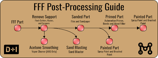
Figure 1. A diagram of the planned layout for the finished display.
In order to best showcase these different methods, we have begun designing a 3D printed part that will allow us to demonstrate the different methods and their advantages and disadvantages. Figure 2 shows that part. This part features curved and flat surfaces to showcase the different effects of sanding. It also has an overhang which will require support and a triangular hole that can be printed without supports. Finally, it has embedded lettering and bolt holes for mounting. We intend to print these mostly in PLA, but one in ABS to showcase acetone smoothing. This is because PLA is the most commonly used material for FFF 3D printing at the Makerspace.

Figure 2. The first iteration of the test part used to showcase different post-processing methods
Proposed first steps
Our first steps are to ensure that our 3D printed part meets the desired specifications to showcase the post-processing methods we intend to use. The part will be relatively small, within a 5-inch cube, meaning that we should be able to print multiple of them very quickly. We will use the Bambu slicer to determine the optimal settings (infill, layer height, etc.) for this part and the support type. Then, we will be able to print as many of these example parts as needed.
Additionally, we will need to acquire the supplies for each of the methods, such as acetone, sandpaper, wood filler, and paint. We will also be researching other possible post-processing methods that could be done at the Makerspace and determining whether they are viable additions to the display. Once we know how many post-processing techniques we are going to display, we can print out our example parts. Then we can follow the flow chart and perform the different post-processing methods on them.Once those are finalized, we will use the CNC router to make the display board and mount our finished example parts to it.