Project Overview:
To transition 3D printed components from prototypes to functional end-use products, understanding the mechanical anisotropy caused by the Fused Filament Fabrication (FFF) technique is vital. The mechanical properties of parts produced via FFF are significantly affected by factors such as build orientation, layer height, and feed rate. Thus, comprehending the specific impact of these parameters on printed parts’ mechanical properties is crucial. Utilizing the resources at the Polymer Engineering Center, our project aims to investigate the effects of build orientation, layer height, and feed rate on the mechanical anisotropy of polylactic acid (PLA) and acrylonitrile butadiene styrene (ABS) components produced by FFF. Our primary focus is on assessing the tensile modulus and strength to enhance the mechanical performance of these materials.
Introduction:
FFF is the most popular 3D printing technique for polymeric materials, favored for its low cost, simple process, and versatile printing capabilities [1]. However, gaps or voids between layers can lead to mechanical anisotropy in FFF parts [2]. Printing parameters such as build orientation, layer height, and feed rate also influence this anisotropy. To achieve high-quality FFF parts, it is crucial to study the relationship between printing parameters and the anisotropic mechanical properties of 3D printed parts.
PLA and ABS are commonly used materials in FFF. Structurally, PLA contains soft ester groups in its backbone, making it more flexible, whereas ABS exhibits strong intermolecular forces due to polar nitrile and phenyl groups. These forces facilitate phase separation in ABS resin, which consists of a continuous styrene-acrylonitrile matrix and a dispersed phase of polybutadiene particles [3]. Thus, under identical printing conditions, PLA chains are more easily stretched and aligned than those of ABS. Consequently, PLA is expected to exhibit greater mechanical anisotropy than ABS at the molecular level.
Objectives:
Our goal is to explore how build orientation, layer height, and feed rate affect the mechanical anisotropy, including tensile modulus and strength, of PLA and ABS parts manufactured through FFF printing. Additionally, we aim to compare the mechanical anisotropy between PLA and ABS materials. This project is expected to enhance our understanding of FFF’s advantages and limitations in practical applications, offering deeper insights into its wider industrial use and promotion.
Preliminary Design:
- Conduct preliminary tests on FFF printers, PLA materials, and tensile testing equipment to ensure the work environment and workflow are stable.
- Initially use FFF to print thin samples for tensile testing, adjusting printing parameters like build orientation, layer height, and feed rate. Produce multiple copies of each sample set for repeat experiments.
- Perform tensile tests on these samples, repeating the experiment three times for each type of sample. Then, analyze the results.
- Should the project advance smoothly, we’ll extend our analysis to the mechanical performance of ABS material samples, assessing how these printing parameters differentially affect the mechanical properties of PLA versus ABS samples.
Preliminary Testing:
In the experimental setup phase, we need to verify the availability of FFF printers and materials at the Polymer Engineering Center.
- We will first determine the molecular weight and chemical composition of commercial PLA and ABS filaments using gel permeation chromatography (GPC) and nuclear magnetic resonance (1H-NMR), respectively.
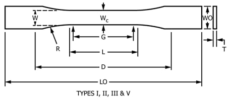
- Further verification of the FFF equipment is necessary. For tensile testing, we will use an Instron 5967 universal testing machine with a 30 kN load cell according to ASTM D638-14 standard. Calibration of the initial workflow will be finalized before formal testing begins. The sample size should be well printed to adjust to the testing platform (parameters need to be determined in preliminary testing)
Next Step:
Print the samples and do tensile test!
Tensile Testing Table
| Sample ID | Material Type | Build Orientation | Layer Height (mm) | Feed Rate (mm/s) | Tensile Strength (MPa) | Tensile Modulus (GPa) |
|---|---|---|---|---|---|---|
| PLA | 0° | |||||
| PLA | 90° | |||||
| PLA | … |
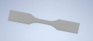
Sample Shape
References:
[1]. Singh, Sunpreet, et al. “Current status and future directions of fused filament fabrication.” Journal of Manufacturing Processes 55 (2020): 288-306.
[2]. Ghorbani, Jafar, et al. “Eliminating voids and reducing mechanical anisotropy in fused filament fabrication parts by adjusting the filament extrusion rate.” Journal of Manufacturing Processes 80 (2022): 651-658.
[3]. Campo, E. Alfredo. Selection of polymeric materials: how to select design properties from different standards. William Andrew, 2008.