Christina Harmon, Christopher Lawrence, Justin Tan, Oliyad Dibisa, Tommii Zeng
Project Background
The goal of this project is to find out if high-density polyethylene (HDPE) vitrimer can overcome the shortcomings of regular HDPE during the 3D printing process. This includes warpage, self-adhesion issues, and more [1] . The material choice for HDPE is HDPE F04660 supplied by SABIC. The HDPE vitrimers were prepared using reactive blending of maleic anhydride-grafted-polyethylene (PE-MAH) and 4,4’ dithiodianiline (DTA) as the crosslinker. The material of choice for HDPE vitrimer is HDPE-V0.3 which represents 0.3% wt. of MAH and a molar ratio of MAH:DTA of 1:0.5. Parameter optimization was done using Simplify3D, and printing was performed with Cosine, a screw-based additive manufacturing machine. HDPE and HDPE vitrimers have similar printing properties, such as melt temperature and crystallization temperature. Due to the high price of manufacturing HDPE vitrimer, HDPE was chosen as the tuning material.
For testing the mechanical properties of the 3D-printed HDPE and HDPE-vitrimer parts, DMA frequency sweeps using a Netzsch Eplexor 500N DMA machine were performed instead of tensile tests. Frequency sweeps will be performed in the linear viscoelastic regime among all samples for more accurate results due to the viscoelastic and time/frequency-dependent nature of polymers. Therefore, the sample size was scaled down to 20mm*40mm*3mm. An engineering drawing of the new test specimen dimensions is shown in Figure 1.

Initial Print Result
Initial printing parameters were referenced from filaments.ca, where individuals share and discuss the optimal settings for 3D printing with HDPE filaments. The nozzle diameter will be controlled at 1mm throughout the experiment. The first batch of successfully printed test samples of HDPE was printed using the parameters shown in Table 1.

Defects were observed and presented in Table 2.

Print Optimization
Optimizations were made to address the defects observed when printing with HDPE. The melting and crystallization temperature for HDPE F04660 – SABIC is 138°C and 115°C, respectively. A bed temperature of 135°C would ensure that the material is above the crystallization temperature so the material sticks to the bed with no warpage present during the printing process. However, such a high print bed temperature creates a melt pool in the first layer of printed materials. Even though a lower temperature difference between the nozzle and print bed is recommended, lowering the bed temperature to 60°C is most suitable for HDPE printing. Observations are presented in Table 3.

At a bed temperature of 60°C, adhesion became a significant issue. Print bed material optimization was performed by selecting various substrate materials and testing them under the same bed temperature. Materials were taped onto the aluminum print bed and heated to 60°C. Adhesion of the bed material with HDPE has been documented in Table 4.

Polypropylene (PP) Sheet with a thickness of 1/16’’ was chosen as the best substrate material for HDPE 3D printing. Unlike LLDPE, PP provides just enough adhesion, allowing HDPE to stick to it but not bond to it. A thickness of 1/16’’ ensures better heat dissipation so that it does not warp whereas a thickness of 0.03’’ was too thin and resulted in warpage. When printing with PP substrate, a heat gun should not be used since it can quickly deform the material.
At the final tuning stage, brim was added to the printing design to further eliminate warpage and increase the adhesion of HDPE samples. It was found that having at least five brim layers significantly reduces the warpage at the edge of the sample. A direct comparison of samples with and without brim is shown in Figure 2.

The final printing parameters determined for HDPE 3D printing are shown in Table 5.

The same parameters were applied when printing HDPE Vitrimers. However, due to the higher viscosity of the material, not enough material extruded out of the nozzle, causing gaps between each bead. A higher extrusion multiplier was applied to compensate for the insufficient extrusion but this introduced a new defect, melt fracture, shown in Figure 3.

Melt fracture is usually observed when the residence time (processing time) is lower than the relaxation time. Therefore, the extrusion multiplier was decreased to lower the residence time. Further experiments will be conducted to measure the relaxation time of the HDPE vitrimer in the melt state. The residence time in the 3D printer will also be quantified with a color tracer. Trials of vitrimer printing are displayed in Figure 4. HDPE-V0.3 has a yellow to brown appearance due to the cross-linked chemistry.

The final printing parameters used for HDPE vitrimers are shown in Table 6.

Result
Test specimens with orientations of 0°, 45°, and 90° were printed with the printing parameters shown in Table 5 and Table 6 for HDPE and HDPE vitrimer (Figure 5).

Samples are trimmed to desired dimensions in order to exclude the build-up of material on the perimeter of each sample and to meet the DMA machine size requirement. Samples for DMA testing are displayed in Figure 6.

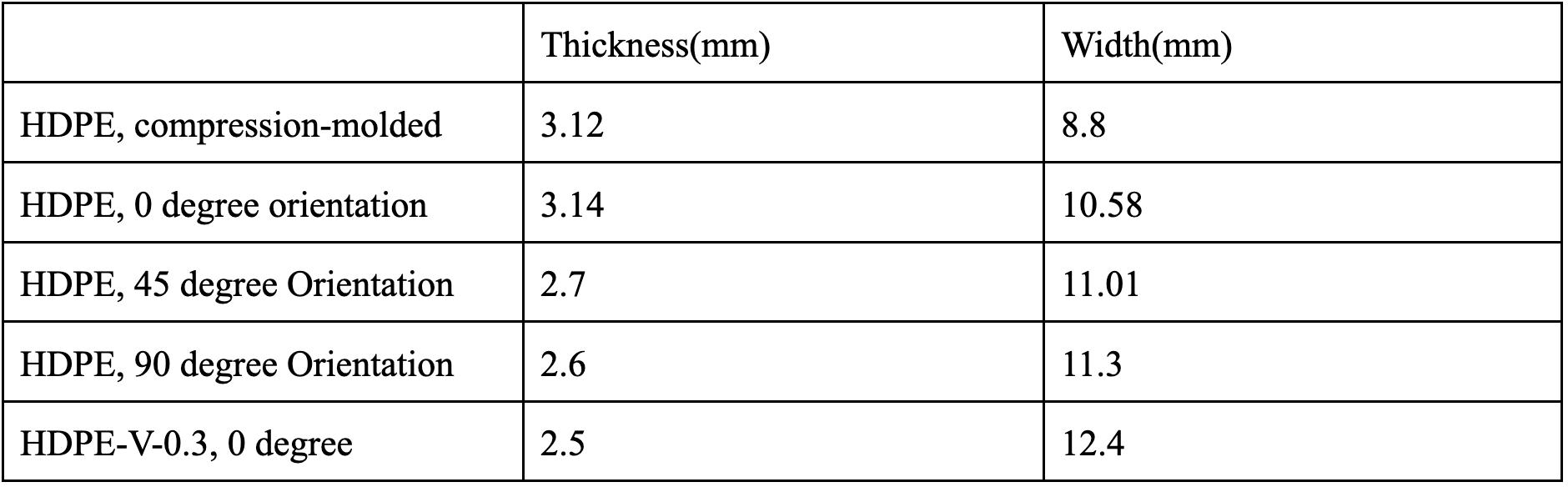
DMA frequency sweeps were used in place of tensile tests due to the viscoelastic and time-dependent nature of polymers. The frequency sweep introduces stress and strain into polymer samples at varying rates and gathers information on the viscoelastic response of the samples at different time scales. Frequency sweeps were performed on HDPE and HDPE vitrimer samples with dimensions specified in Table 7 using a Netzsch Eplexor 500N DMA.
Prior to frequency sweeps, dynamic strain sweeps were performed on each sample at room temperature to define the limits of the linear viscoelastic regime (LVR) where the complex modulus E* is constant. A dynamic strain was then chosen within the LVR for the frequency sweeps. The dynamic strain limits and the strain used in the frequency sweeps are shown in Table 8. Frequency sweep and dynamic strain sweep results of HDPE are shown in Figure 7.
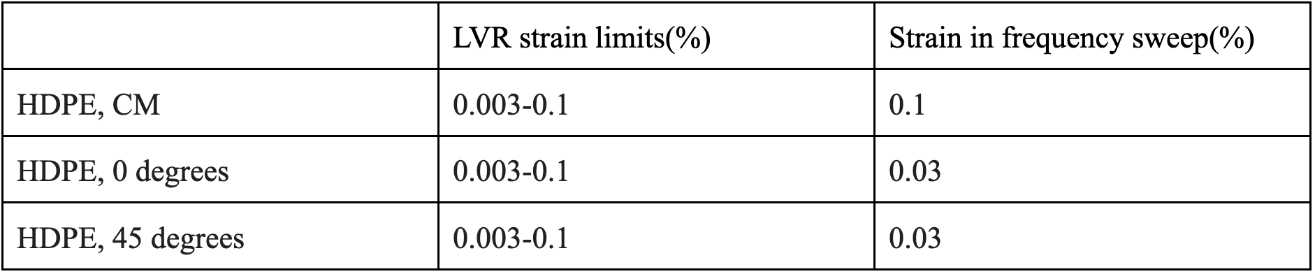
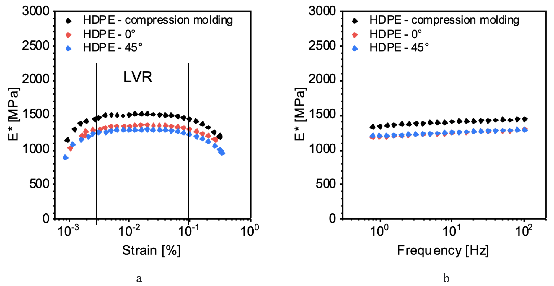
Figure 7a shows that E* for both HDPE 0 degree orientation and HDPE 45-degree orientation drop as percent strain increases above the LVR. A percent strain value of 0.03 was used in frequency sweeps of both samples. Figure 7b shows that for all samples, E*increases with increasing frequency. These results reflect the time-dependence of polymers: at higher frequencies or smaller time scales, the samples have less time to recover from the applied stress, and thus behave more solid-like, as characterized by higher E*; at lower frequencies or larger time scales, the samples have more time for stress relaxation and thus lower E* values are recorded. Comparing samples prepared by different processes, the compression-molded sample shows the highest E* throughout the entire frequency range; samples printed with 0 degree and 45-degree orientations have similar E* values which are consistently lower than the compression-molded sample. The differences in E* between the 3D printed samples and the compression-molded sample are as we expected, and we expect that a 3D printed sample with a 90-degree orientation would show similar E* values to the compression-molded sample.
Future Work
The first stage of the project, tuning the 3D printer, is complete. The focus for the remainder of the project will be sample testing and comparison. DMA frequency sweeps will be performed on all samples and characteristic curves for the two materials will be compared. The printing process will be revised for both materials to develop a better plan to compare the warpage without interference. Furthermore, shrinkage tests will be replaced by “post-curing” tests due to difficulties.
References
[1] Spoerk, Martin, et al. “Material Extrusion?Based Additive Manufacturing of Polypropylene: A Review on Ho]w to Improve Dimensional Inaccuracy and Warpage.” Journal of Applied Polymer Science, vol. 137, no. 12, 2019, p. 48545., https://doi.org/10.1002/app.48545.