Project Update: 3D Printed Tactile Maps for the UW-Madison Engineering Campus
Group 8: Hayden Eisenreich, Isabelle Hanson, Saketh Sridhara, Mikolaj Tyksinski
Updated Design
One update we made to our design was the addition of fillets along every edge of the model. Fillets create smoother transitions between faces providing a better user experience. An updated image of our model is shown in Figure 1 below.
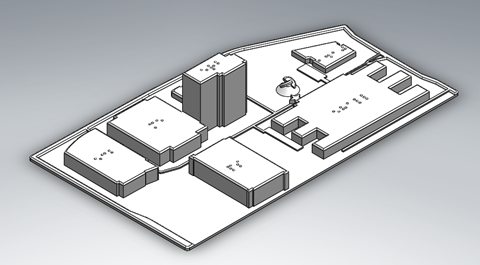
Figure 1: Updated design of the campus map.
Another design change that was made was the size of our model. A scaled down version was created for printing on the SLA printer. Our full-size model is 6.25” x 9”. This is too large to fit on the SLA printers at the makerspace. The model size was scaled down to 56% and the braille had to be remolded to maintain the standard size. Braille indicators on the top of 1410 Engineering Drive were not able to fit on the smaller model shown below in Figure 2.
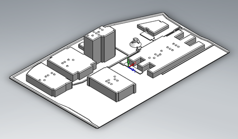
Figure 2: Smaller version of the campus map for SLA printing. Note: No markings on top of 1410 Engineering Drive.
Four trials were completed to analyze printability of our design. These trials will help us determine the best printing process for our project. Print settings and individual trial goals are explained in detail below.
Print Trial #1
We began our print trials by printing the updated CAD model with the FFF technique, using the Ultimaker S5 machine at the Makerspace. The print parameters for this first trial are outlined in Table 1.
Table 1: Print parameters for trial #1.
| Trial #1 | |
| Purpose/Variable of Interest: | Testing quality of print using FFF. |
| Process/Machine Used: | Ultimaker S5 |
| Material Used & Amount: | PLA White; 99 g |
| Cost of Material: | $0.08/g |
| Print Dimensions: | 245.4 mm x 162.3 mm x 42.5 mm |
| Print Orientation: | Flat on the build plate (0-degrees) |
| Layer Height: | 0.3 mm (extra fast print speed 86 mm/s) |
| Infill Percentage: | 20% |
| Support Necessary: | None |
| Time to Complete: | 8 hr 00 min |
For the first print, our objectives were: (1) ensure that the part is printable within 8 hours and (2) identify the potential failure modes and gauge print quality of braille. To ensure fast print time, we used an extra fast print speed of 86 mm/s and a 20% infill rate. While the braille had been modeled as per the ADA standards, we wanted to ensure it could be printed as accurately as possible. Thus, we considered 3 printing layers for the braille (on the top layer). The printed tactile map is shown in Figure 3.
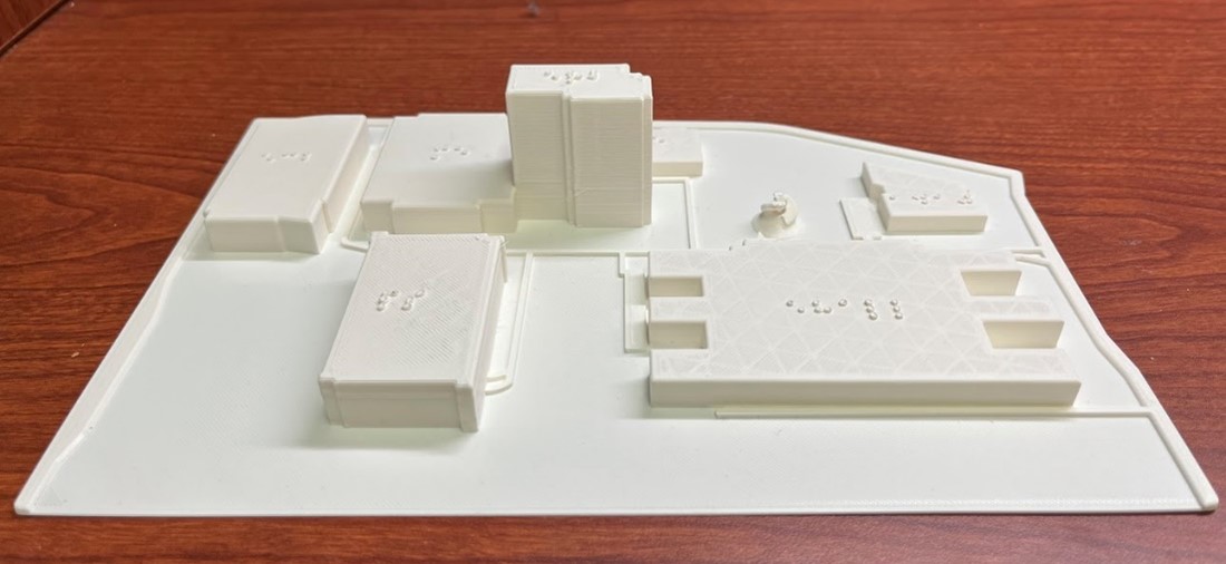
Figure 3: Tactile map of the Engineering campus using the trial 1 print parameters and the FFF process.
While the tactile map accurately represented the heights of the engineering campus buildings, we observed that the FFF process could lead to serious issues with the braille printing under the parameters from trial 1. Specifically, we noticed (as seen in Figure 4) that the braille font is no longer consistently circular, and there is also some intra-braille bleeding and overlapping characters with no/poor spacing. This leads to difficulties in reading braille, rendering these tactile maps unusable for the visually impaired. Also, the defects were not consistent across the part – braille characters on some buildings printed better and with fewer defects than the braille on Engineering Research Building. The printing resolution offered by the 0.4 mm nozzle at fast print speeds is neither reliable nor robust for braille applications, and we may further need to tune parameters such as print speed, layer height, and nozzle diameter to check if FFF is amenable for printing braille.
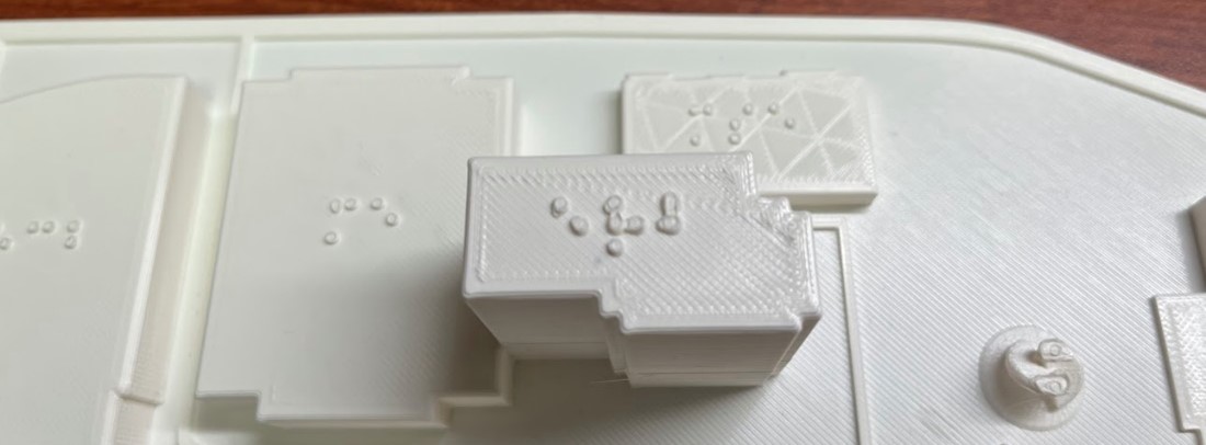
Figure 4: Issues with Braille: circular shape and spacing not preserved, overlapping characters (bleeding).
Another issue noticed with print trail 1 is the flexing of the base of the tactile maps, as seen in Figure 5. This can lead to poor structural strength and breakage upon mounting or drops. This is less of a printing or material issue and can be attributed to the design thickness. Thus, we intend to fix this design issue with a thicker base plate for future trials.
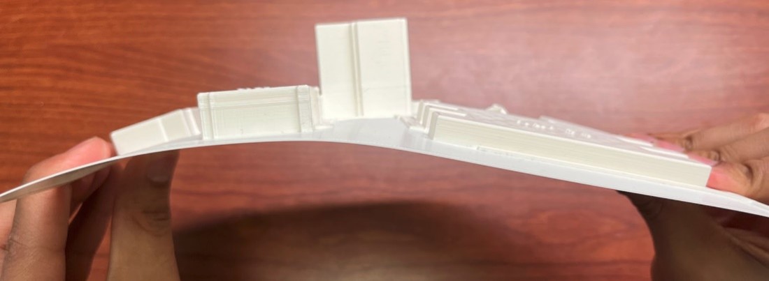
Figure 5: Inadequate base thickness leading to flexing of the tactile map.
Print Trial #2
The second print trial that we ran was to test the quality of printing with SLA. We used the Form 3 SLA printer at the Makerspace with the Grey V4 resin. The main print parameters for this trial are outlined in Table 2.
Table 2: Print parameters for trial #2.
| Trial #2 | |
| Purpose/Variable of Interest: | Testing quality of print using SLA |
| Process/Machine Used: | Formlabs SLA (Form 3) |
| Material Used & Amount: | Grey V4 Resin; 81.08 mL |
| Cost of Material: | $0.26/mL |
| Print Dimensions: | Full model, scaled down; 137.4 mm x 90.9 mm x 24.0 mm |
| Print Orientation: | Auto-oriented angle per Makerspace staff suggestion |
| Layer Height: | 0.100 mm |
| Infill Percentage: | 100% |
| Support Necessary: | Yes |
| Time to Complete: | 5 hr 30 min |
To print using the Form 3 machine, our model had to be scaled down to fit within the build plate dimensions. Because of this adjustment, the braille on top of 1410 Engineering Drive was not included and the braille on top of most of the other buildings was closer to the edges than may be acceptable for a visually impaired user. Additionally, when slicing the STL file at the Makerspace, the staff suggested that we print our model at the auto-oriented angle and generate supports to reduce the force required to lift the cured part out of the resin vat. Initially, we wanted to print the model at a 0-degree orientation to be consistent with our other trials, however, this was not advisable because the larger layer size at 0 degrees subjects the part to high forces and can result in more warpage or inaccurate geometry. The top view of our final print is shown below in Figure 6 and the side view with supports still attached is shown in Figure 7.
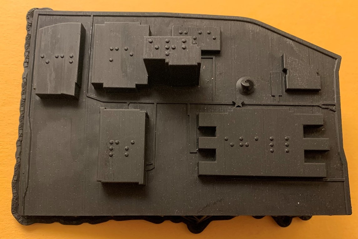
Figure 6: Top view of final printed part using the trial 2 print parameters and the SLA process.
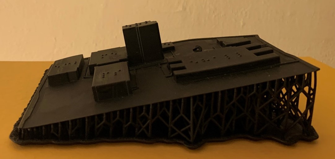
Figure 7: Side view of final printed part using the trial 2 print parameters and the SLA process.
As can be seen from Figure 6, the quality and fine details of the print turned out quite well, particularly the braille, as it is accurately spaced relative to the other braille characters and does not run together. Additionally, upon touching the braille, you can feel each of the individual characters and clearly differentiate them from the top of each of the buildings. Turning to Figure 7, it can be seen that a lot of support material was required to print the model at the auto-oriented angle. It is worth noting that we chose not to remove these supports for two reasons – one being to clearly show the amount of support material required, and the other being to avoid causing damage to the thin base of the model. While printing at an angle and using supports did decrease the force required to lift the model from the resin vat, it added to the print time and cost which is not ideal considering our project constraints. If future trials are run using the SLA process, it would be worth discussing with the Makerspace staff to see if a smaller angle could be used or if any angle at all is truly necessary.
Although the quality of the braille and fine details of this print are favorable, there are a few drawbacks to using this printing process. First, upon close inspection of Figure 6, you can see small ridges running perpendicular to the length of the part on the flat surfaces. While this may not be problematic to users without visual impairments, it may confuse those who are visually impaired as the surfaces are not completely smooth and could potentially be mistaken for a textured surface that we are not trying to convey. Another issue with printing using the SLA process is the build plate limitations. As was previously mentioned, we had to scale down our model to fit on the build plate which resulted in the braille on top of a few of the buildings, particularly Engineering Centers Building, Engineering Research Building, and the Material Science & Engineering Building, being closer to the edges than initially intended. Additionally, scaling down our model did not allow us to include braille on top of 1410 Engineering Drive in any capacity. While this is clearly an issue, the other two drawbacks may or may not be issues for our visually impaired users and moving forward we would like to get feedback from someone with a more sensitive touch to confirm or deny whether these are issues that we should focus on improving in future trials.
Print Trial #3
After our first 2 trials we decided to focus on the accuracy of the braille on top of the buildings while utilizing a larger scale, and faster print process than SLA. To do this more quickly we designed a test model consisting of only the parking structure with an additional test braille cell with all dots filled. This simplified model is depicted in Figure 8 below.
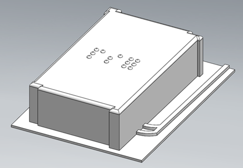
Figure 8: 3D view of the simplified parking structure test model.
The print parameters for this trial are outlined in Table 3.
Table 3: Print parameters for trial #3.
| Trial # 3 | |
| Purpose/Variable of Interest: | Test improved resolution and accuracy of the Stratasys FFF 3D printer
Print speed: Default |
| Process/Machine Used: | Stratasys F370 FFF |
| Material Used & Amount: | ABS; 1.37 cubic inches |
| Cost of Material | $2.96 / cubic inch |
| Print Dimensions: | Parking Ramp only; 63 mm x 47 mm |
| Print Orientation: | Flat |
|
Layer Height: |
0.005” (0.127 mm) |
| Infill Percentage: | 52% |
| Support Necessary: | Raft |
| Time to Complete: | 1 hr 28 min |
We selected the Stratasys F370 FFF printer for another model run because its closed chamber may help reduce the effects of the outside environment, allowing for better humidity and temperature control. We were interested in if this would help with reducing the bleeding or overlapping effect across braille letters in our previous FFF model.
In addition, the Stratasys features relatively high accuracy, allowing layer thicknesses of 0.127 mm with ABS and ASA, and “accuracy of +/- .200 mm (.008 in), or +/- .002 mm/mm (.002 in/in), whichever is greater” [1]. The large build volume of the Stratasys at 355 x 254 x 355 mm exceeds that of even the Ultimaker S5, allowing for the model to be printed at its original scale or even be expanded upon if desired in the future. With this we do not need to sacrifice the design and size as was the case with the Formlabs SLA printer.
We also are interested in ABS as an alternative material because of its higher glass transition temperature than PLA allowing for more robust use outdoors with hot temperatures in the sun [2]. ABS is also considered tougher and more durable than PLA. With the Stratasys printer we can use ABS and create a more robust part.
Results of the print can be seen in Figures 9 and 10 below. Accuracy is significantly improved over the Ultimaker FFF part, with clear braille characters free from any overlapping. Further evaluation of the characters is needed with the McBurney Center to see whether they are legible, but initial results are promising. In addition, filleted surfaces came out sufficiently soft on the edges.
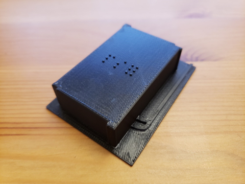
Figure 9: 3D view of the completed Stratasys parking structure model.
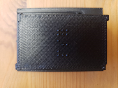
Figure 10: Top view of the completed Stratasys parking structure model depicting the braille accuracy.
The high accuracy of the Stratasys print, use of ABS material for weatherproofing, and its ability to print larger parts quickly have led our group to decide that further pursuit of the Stratasys printer is best for our part application.
Print Trial #4
Print trial 4 utilized the same simplified model of the parking garage as in trial 3. For this trial, we used an Ultimaker 3 FFF printer at the finest detail settings possible to determine if high quality braille could be produced. The settings are outlined in Table 4 below.
Table 4: Print parameters for trial #4.
| Trial # 4 | |
| Purpose/Variable of Interest: | Generate baseline for maximum quality of Ultimaker Printers/Layer Height and Print Speed
Print Speed: 45 mm/s |
| Process/Machine Used: | Ultimaker |
| Material Used & Amount: | PLA 15g |
| Cost of Material: | $0.08/gram ($1.20 for the part) |
| Print Dimensions: | Parking Ramp only; 63 mm x 47 mm |
| Print Orientation: | Flat |
| Layer Height: | .06 mm |
| Infill Percentage: | 20% |
| Support Necessary: | No |
| Time to Complete: | 3 hr 34 min |
The primary difference between trial 4 and trial 1 was print speed and layer height. In general, lower print speeds improve part quality at the expense of overall print time. Thinner layer heights allow for more detailed small features because geometry changes can be matched better with higher resolution. However, thinner layer height also adds to overall print time. Figure 11 below shows how finer layer height can produce higher quality small features.
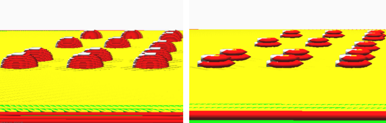
Figure 11: The left image depicts a layer height of 0.06 mm. The braille is printed in 9 layers allowing the spherical shape to be closely matched. The right image depicts layer height of 0.2 mm. The braille is printed in 2 layers resulting in a non-spherical shape.
If settings optimized for quality produce braille that is deemed “acceptable” Ultimaker machines could potentially be used to lower the overall cost of the project as Ultimaker filament is approximately four times cheaper than Stratasys filament. Exceptions would need to be made for the overall print time requirement of the project (maximum 8 hours) because the full model printed at these settings would take 36 hours. The results of trial 4 are depicted in Figure 12 below.
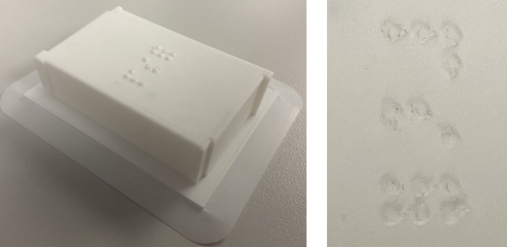
Figure 12: The left image depicts the overall model. The right image is a close up of the braille. Merging of the cells is most visible in the bottom braille cell with 6 domes.
Even at the finest detail setting, there were issues with the braille shape. Some individual domes merged creating legibility concerns. Our conclusion from this test is that the Ultimaker FFF printer is unable to produce prints at the quality we require for this project.
Future Considerations
Moving forward, our primary goal is to set up a meeting with the McBurney Disability Resource Center to receive feedback from someone who would potentially use our tactile map. We would like to get their thoughts on whether our braille is appropriately spaced and accurately readable. We would also like to ask them whether the surface textures of our prints cause any confusion, if any of the edges or corners are too sharp, and if they have any other suggestions that would make our maps more user friendly. We have been in contact with the McBurney Alternative Formats Coordinator, and we are in the process of setting up a meeting with both them and someone who reads braille.
Additionally, since the Stratasys FFF printer provided the best quality for our model and particularly for the braille, we would like to run a future trial with the full model using this machine. Our hope is that the use of the full-size model along with the higher quality printer will result in a smooth, uniform, and easily readable tactile map that visually impaired users will be able to use effectively. Another parameter that we would like to explore is looking into the other materials that the Makerspace has available for this machine and experimenting with one that would be most appropriate to be used in an outdoor setting for an extended period. Since our goal is to display our complete tactile map outside of Engineering Hall, we need to print with a material that is not only strong enough and able to produce fine details but is also able to endure the elements. We believe that the Stratasys FFF printer will allow us to accomplish each of these things, so moving forward, trials with this printer will be our focus.
Resources
[1] “Stratasys F370.” Objective 3D, https://www.objective3d.com.au/stratasys-f370/
[2] “ABS.” All-In-One 3D Printing Software, Simplify3D Software, 24 June 2019, https://www.simplify3d.com/support/materials-guide/abs/