Project Overview
A glass furnace expels very hot air during its operation. It also takes in relatively cold air in order to operate, using large amounts of energy to maintain operational temperatures. By installing a recuperator, the waste heat would be reduced and the furnace would operate with greater efficiency. Figure One illustrates this effect with a diagram of how a basic recuperator operates. By using additive manufacturing processes, very effective heat exchangers may be designed and used for this purpose that would otherwise be impractical to fabricate through other means.
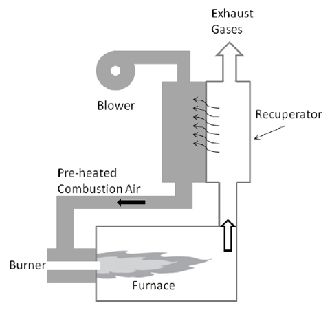
Figure One: Furnace Recuperator
Introduction
A member of this team has a glass blowing shop with a natural gas burning melt furnace. This furnace melts glass at temperatures up to 2200F (1200C) and must run continuously to avoid thermal shock of the ceramic crucible. This furnace is pictured in Figure Two. Optimizing the furnace for fuel efficiency would lower its operational costs and reduce its carbon footprint. One solution for this would be adding a heat exchanger for use in converting the burner assembly into a recuperative system. This means the exhaust heat could be used to preheat the intake air of the burner. This would lower the total thermal energy required from combustion for maintaining the target temperature, thus increasing the total efficiency of the system.
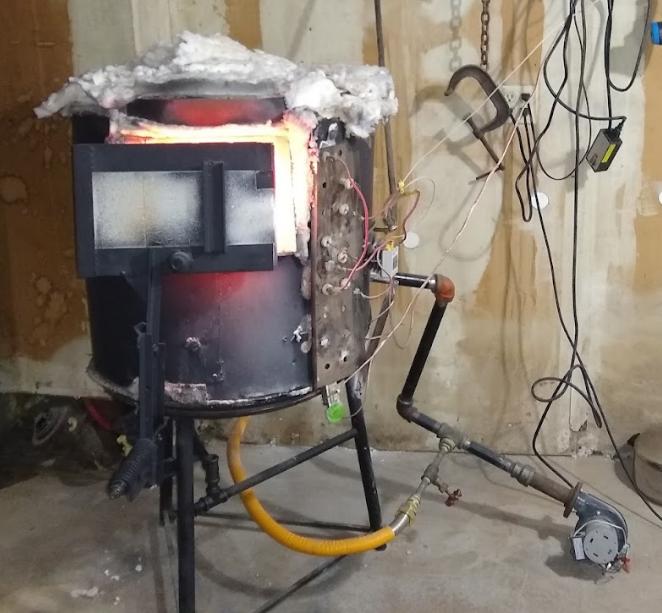 Figure Two: Furnace that Recuperator Will be Implemented On
Potential Materials
Table one shows a selection of metals that the available 3D printers are capable of printing in. Melting temperature of these metals is of particular interest as the heat exchanger would need to withstand temperatures up to 2200F (1200C) without melting. Density is also relevant as it determines the weight of the part.
|
Material |
Density | Melting Temperature | Printers |
|
Stainless 316L |
0.29 lbm/in^3 (8.03 g/cc) | 2540 – 2540 F (1390 – 1440 C) | EOS M290 & Lens MR7 |
| Titanium | 0.163 lb/in^3 (4.50 g/cc) | 3000 – 3040 F (1650 – 1670 C) |
Lens MR7 |
| Aluminum | 0.009704 lb/in^3 (2.70 g/cc) | 1220.7 F (660.37 C) |
EOS M290 |
Table 1: Printable Materials and Properties [1][2][3][4]
The best material candidate for printing would most likely be stainless steel. An aluminum setup would likely melt and titanium would likely be unnecessarily expensive. Additionally, exhaust gases may cause oxidation in materials susceptible to corrosion.
Analysis and Testing
Instrumentation for data collection required for both the design and the verification of the heat exchanger’s functionality will be required. Using type K thermocouples and a pitot tube pressure differential flow meter, temperature, flow rate and pressure data can be obtained for finding design specifications and ballpark constraints. A testing apparatus (essentially a pipe) with these devices can be constructed and mounted on the exhaust while the furnace is at its peak temperature. This apparatus could also have a valve such that the cross-sectional area of the exhaust can be varied so that the backpressure required for the burner to create an unstable flame (“sputter”) can be found. For the analysis of the prototype, the fuel flow rate could be measured with a gas flow meter and, at a minimum, four thermocouples can be mounted on the heat exchanger at the inlet and outlet of both the exhaust and intake air. Currently gas is exhausted through a small square hole in the side of the furnace which can be seen in Figure Three.
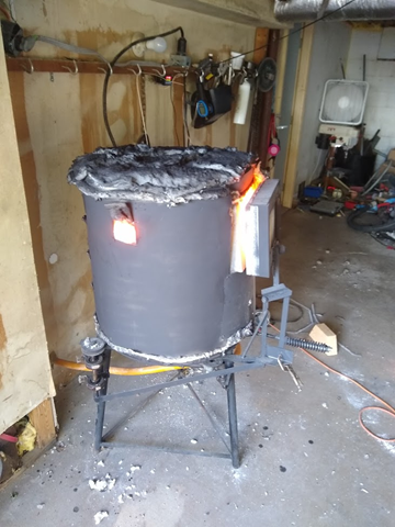 Figure Three: Furnace Exhaust Hole
Sources:
[1]
“Stainless 316, 316L, 317, 317L.” United Performance Metlas. [Online]. Available: https://www.upmet.com/sites/default/files/datasheets/316-316l.pdf
[2]
Alloy Design and Development Laboratories, “Laboratory Capabilities,” Thoma Research Group, [Online]. Available: https://thoma.msae.wisc.edu/laboratory/
[3]
“Aluminum, Al Data Sheet,” MatWeb, [Online]. Available: http://www.matweb.com/search/DataSheet.aspx?MatGUID=0cd1edf33ac145ee93a0aa6fc666c0e0
[4]
“Titanium, Ti Data Sheet,” MatWeb, [Online]. Available: http://www.matweb.com/search/DataSheet.aspx?MatGUID=66a15d609a3f4c829cb6ad08f0dafc01&ckck=1
[5]
“About Us Page,” Conflux Technology, [Online]. Available: https://www.confluxtechnology.com/about-us
[6]
Amiri, A. and Vaseghi, M., 2015. Waste Heat Recovery Power Generation Systems for Cement Production Process. IEEE Transactions on Industry Applications, 51(1), pp.13-19.
[7]
“Heat Recuperators” GLASS SERVICE – Solutions For The Glass Industry. (n.d.). Retrieved March 2, 2022, from https://www.glassservice.it/en/products/heat-recuperators/46/