Project Background
The proposed project is a functional prototype for a newly designed automobile suspension system. The product is based on a double-wishbone suspension structure with a redesigned upper suspension arm. The suspension system can provide vehicles with a dynamically adjustable camber angle by changing the length of the upper suspension arm, in turn, creating a better performance for race cars, and a better driving experience for daily automobiles.

The camber angle of wheels is highly influential on vehicle control. Both positive and negative camber angles can be advantageous. However, conventionally the camber angle is set during wheel alignment and this angle cannot be adjusted while the vehicle is in motion. Our design allows for on-road camber angle adjustments based on the compressive forces on the wishbone structure.

A negative camber increases the contact area between the wheels and the road while cornering. The increased traction between the wheels and the road allows for a more stable ride that is not available with traditional suspension systems alone. A positive camber provides more stability while traveling in a straight line. Both camber angles have advantages that can be exploited with our design. In addition to the stability that adjustable camber angles provides, the wishbone suspension system provides more freedom of damper placement, which is desirable in race cars where aerodynamics is highly influential.
The project involves an iterative process where the thermal and machining properties of the materials and the dimensional tolerances of the design will be evaluated to find the best combination for the production of an accurate functional prototype. Additive manufacturing has been chosen to manufacture the prototype because of the ease of low-cost development of iterations, and investigations into the material properties.
Design and Manufacturing Considerations
The design is built upon a double-wishbone compressible suspension system. This system was chosen as the baseline because of its ability to maintain contact with the road. The adjustable camber will elevate the current system and provide a better on-road experience.
The functionality of the design comes from the adjustable length of the upper suspension arm. The length adjustment of the upper suspension arm occurs when compressive forces are applied to the upper arm. The greater the compressive forces are on the upper arm, the more negative camber is introduced.
The 3D digital model of the suspension system is shown below.

Based on our preliminary design and the material we will use, the key considerations for the design and manufacture of the suspension system are as follows.
- The concept contains moving parts that are required for the prototype to be functional. Movable parts inherently bring failure points to the system. Suspension systems tend to hold the entire weight of the vehicle, and thus massive loads will be applied over the failure points. The design must address this issue and consider how to reduce the failure probability of the moving parts.
- The design must be considerate of the tolerances of the moving parts, and the potential for debris accumulation in these spacings.
- Space for suspension systems is limited, a sleeker, slender design should be prioritized without compromising the strength to hold the vehicle weight.
The chosen process for producing the prototype is additive manufacturing as opposed to subtractive manufacturing. This decision was made based on Design for Manufacturing and Assembly (DFMA). Additive manufacturing is also more sustainable than subtractive manufacturing because of the reduction in waste materials. Another advantage of additive manufacturing is the reduction in time for producing parts compared to subtractive manufacturing, which allows for testing and verification of designs to occur faster.
The printers available for use are fused filament fabrication (FFF) printers and stereolithography (SLA) printers. The FFF printers available for use are ‘ultimaker S3’ and ‘ultimaker S5’, with a maximum printing dimension of 330x240x300 mm. The SLA printers available for use are ‘formlab2’, ‘formlab 3b+’ and ‘formlab 3+’, with a maximum printing dimension of 145x145x185 mm. The available materials for use in the FFF printer are polylactic acid (PLA), PA66/PA6 (nylon), and polyethylene terephthalate glycol (PETG) (3). The available material for use in the SLA printers is clear resin. Based on Formlabs’ material safety manual the clear resin contains urethane dimethacrylate (55-75%), Methacrylate Monomer (15-25%), and photoinitiator (< 0.9%) (4).
For the prototype design, material strength, thermal expansion, and 3D-printer accuracy are the most relevant properties to take into consideration. These variables will be evaluated by test printing functional parts of the prototype and assessing their performance. The properties of the aforementioned materials are listed in the following table.
| Material | Young’s Modulus (MPa) | MAX. Yield Stress (MPa) | Flexural Modulus (MPa) | Flexural Strength (MPa) | Printer |
| PLA | 2346.5 | 49.5 | 3150 | 103 | FFF |
| Nylon | 580 | 27.8 | 463.5 | 24 | FFF |
| PETG | 1939 | 46.2 | 1882 | 78.9 | FFF |
| Clear Resin (post-cured) | 2800 | N/A | 65 | 2200 | SLA |
Table 1: Comparison of material properties (3,4)
Based on the material comparison table, it was decided that PLA would be used in the FFF printers, and clear resin would be used in the SLA printers. PLA was chosen for the FFF printers because it has both the highest Young’s Modulus and yield stress of the available materials. These properties reduce the likelihood of deformation or failure under load. These attributes are desirable for the larger structures making up the main body of the system. Clear resin was selected for the SLA printer because its transparency can reveal the inner structures and details of the design which is beneficial for the demonstrative purposes of the functional prototype.
The pros and cons of each method we will use are detailed in the tables below.
| Fused Filament Fabrication using PLA | |
| Pros | Cons |
|
|
Table 2: Pros and cons of FFF printed PLA (3,4)
| Stereolithography using Resin | |
| Pros | Cons |
|
|
Table 3: Pros and cons of SLA printed resin (3,4)
Proposed Experiments
The key considerations for the printing of the prototype are the sizing considerations and material considerations.
Sizing considerations: Complex structures like ball joints and threads make the prototype difficult to produce in smaller scales. Adding to this, the resolution and detail of certain critical parts might be hindered by printing at smaller scales. Thus, it was decided to print the prototype parts to scale with the largest part having dimensions in the range of 300X200X300mm, near the maximum size of the FFF printers being used.
Material considerations: The key parts in the design that require material considerations have been categorized into structural parts and smaller/moveable parts. The purpose they fulfill in the design and the level of detail required determine the material and process required.
- Structural parts (e.g. suspension arms): FFF Printer with PLA. These parts require strength before other characteristics as they offer basic support for the structure. Changes in size due to the manufacturing process should be kept at minimum, while surface finishing detail is not relevant.
- Smaller/movable parts: SLA printers with clear resin. SLA printers allow for better finishing details, this is required as these smaller parts usually involve moving mechanisms that require precise dimensioning for proper function. This also includes guiding structures, ball joints, screws, and such that involve relative linear and rotational movements. Both high-strength and smooth finishes are required for the smooth movement of the parts.
Another factor that must be considered for the production of the prototype is the slicing software. Through test printing, it was shown that the orientation of parts in printers has a large effect on the quality of products. This factor is more apparent in FFF printers. FFF printers extrude molten material that must be deposited onto a supported structure, e.g. the platform, previously printed material. When some features are overhanging on the main part, an extra support structure must be printed to execute the feature. The grid-like structure of the support structure can result in a bad surface finish of the part once removed. Therefore, it is desirable for support structures to be minimized.
The orientation of parts in the 3D printer can be highly influential for the number of support structures required. As shown below, there can be an orientation (bottom) where support structures are not needed, and a different orientation of the same structure (top), where many support structures are needed.
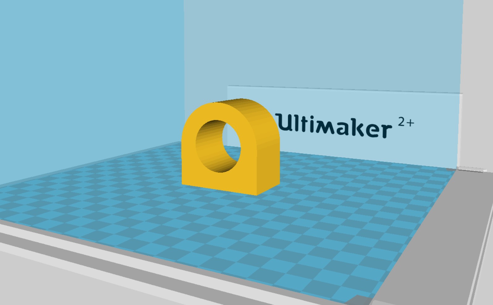
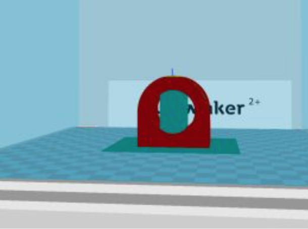
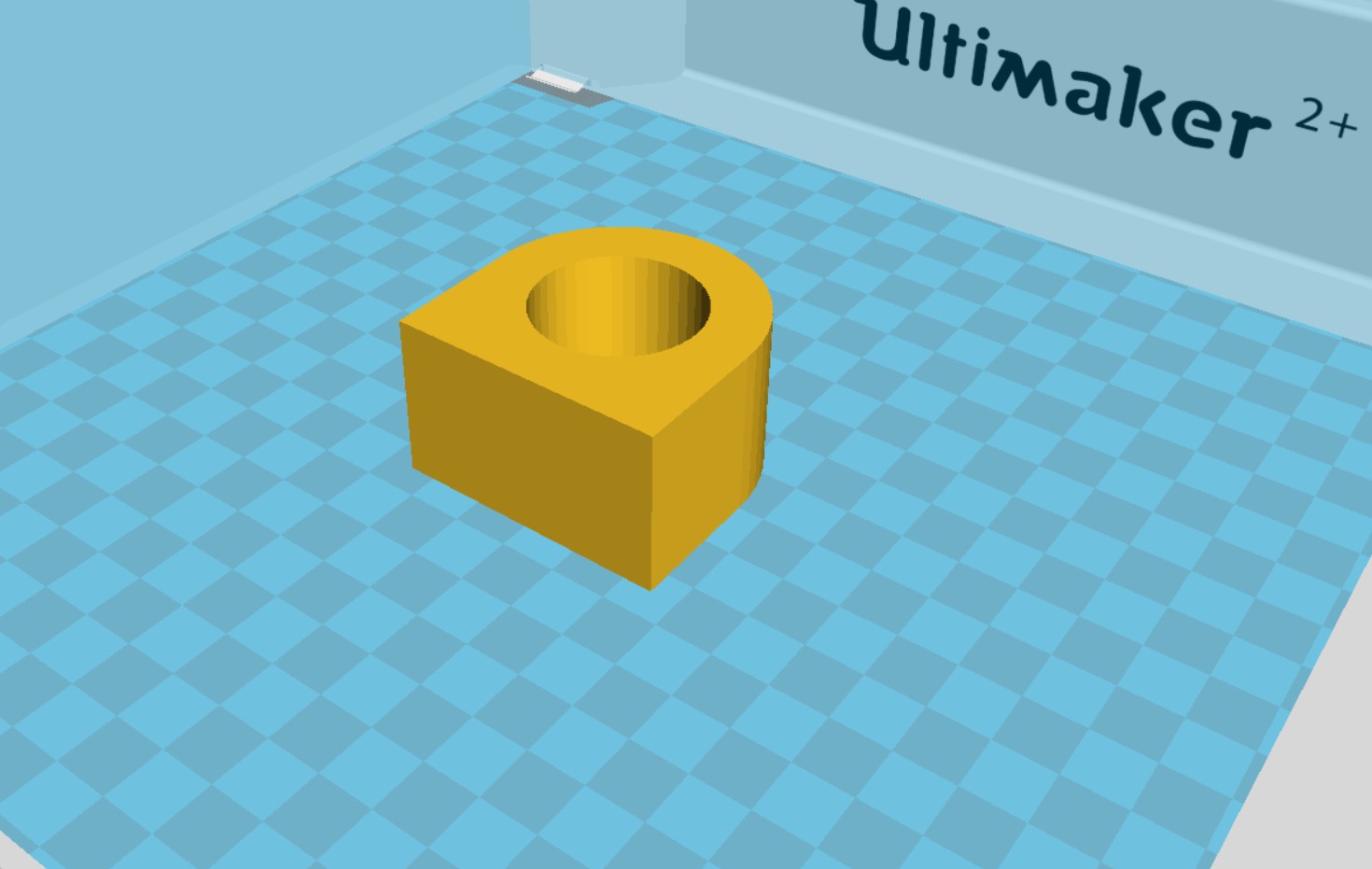
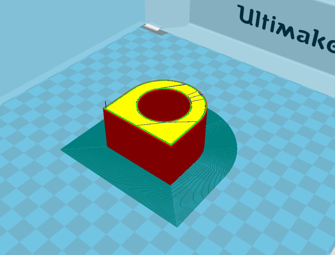
Figure 4: Effect of orientation on support structure requirements
In the top orientation, there is an overhang of the inner circle. Support structures (shown in green) are required to support the overhang. As a result, the surface and the dimension of the inner circle could be compromised. The surface properties of the bottom orientation and the dimensional tolerances of the inner circle are likely to be a lot better. Additional benefits of the minimization of support structures are the reduction in material use and time.
For the proposed design, dimensional tolerances are vitally important for the part to be a functional prototype. Therefore, the orientation of the printed parts for the reduction of support structures is very important.
In the case where the surface finish is not acceptable, we may need to consider post-processing. The post-processing techniques could include, sanding, polishing, painting, etc. If these steps are required, the machining properties of the materials must be considered to ensure that the parts do not fail. Machining property consideration is especially important in thermoplastics like PLA.
Thermal expansion of materials is another key consideration given that multiple materials are being used in this design that have different thermal expansion coefficients. Thermal expansion is especially important for setting dimensional tolerances and designing moving parts. Where possible, parts with dimensional tolerances should be printed using the same material and should allow for extra space for connections. The nature of prototypes allows for some flexibility of the fits, given that the part can still operate as intended. The iterative process of this project will allow for the experimentation of tolerances to produce a structurally sound and functional prototype.
References
- Car Blog India. MacPherson Strut, Double Wishbone And Solid Axle: Dependent and Independent Suspension Systems. Available at: https://www.carblogindia.com/suspensions-macpherson-double-wishbone-solid-axle/
- Mechanic Base. 5 Symptons of a Bad Wheel Alignment (Why you should fix it). Available at: https://mechanicbase.com/suspension/wheel-alignment-symptoms/
- Ultimaker Support. The Ultimaker material technical and safety data sheets. Available at: https://support.ultimaker.com/hc/en-us/articles/360012059859-The-Ultimaker-material-technical-and-safety-data-sheets
- Formlabs Support. Safety with Formlabs SLA printers. Available at: https://support.formlabs.com/s/article/Safety-form2?language=en_US