Justin Bruno, Julio Roldan, Matthew Herro, Kyle Vesely
University of Wisconsin-Madison, Spring 2021
Abstract
Stereolithography (SLA) is an additive manufacturing process that produces water-resistant parts. However, with SLA being an expensive additive manufacturing process method, it is more inaccessible than fused filament fabrication (FFF). In this project, we wanted to determine if a lightweight and durable FFF part could replicate the water-resistant properties of SLA. The desired application for the FFF parts is a cover for an electrical box. The electrical box is attached to a dog wheelchair for Professor Greg Nellis’ dog. To compare different materials using a FFF process Polylactic acid (PLA), Nylon, and Polycarbonate (PC) were used. Different water tests were conducted to test the water tightness to isolate that PLA would be the best material for the desired application. The water tightness test was conducted by filling the parts with a specified amount of water and left overnight. To better test how a part property such as thickness could affect the performance of PLA, parts with varying thicknesses were printed. These parts were then tested with the same water tightness testing to test the impact that the part thickness had. Both parts no water leakage in the water-tightness testing. These parts were then left outside for 24 hours to see the impact that UV rays would have on warpage, as the application will see similar conditions. In this test, the dimensions were taken both before and after, with the thinner part having less warpage than the thicker part. The final test of the parts was a freezing test. This was done to simulate extreme weather in the winter and see how the part reacted. The two parts were filled up with water, put in the freezer, and then removed from the freezer allowing the water to melt and the part’s water tightness after exposure to cold temperatures to be tested. The results of the tests concluded that an FFF process could be used to make a water-resistant cover for the desired application of covering an electrical box. A thinner-walled PLA part was the desired properties of the FFF part and would be sufficient, while also being much cheaper to produce than an SLA part with similar properties and dimensions.
Introduction
Stereolithography is an additive manufacturing process well known for producing water-resistant parts [1]. However, SLA can be significantly more expensive than a more mainstream additive manufacturing process, fused filament fabrication (FFF) [2]. In this project, we wanted to test different FFF materials and vary geometric parameters to create an inexpensive, watertight, lightweight, and durable electronics cover for electronics on a dog cart. Initially, three FFF materials were tested to see which best replicated SLA. Once a material was selected, the thickness was varied to find an optimal thickness based on a second watertight test, a UV warpage test, and a freezing test.
Motivation
The project was inspired by a senior design project for Professor Greg Nellis, a professor in the mechanical engineering department at UW-Madison. The project was in need for a way to keep electrical components from getting wet. The components are for an automated dog wheelchair for his paralyzed dog named Bronte. Her and the cart can be seen in Figure 1. The team wanted to create a cheap, lightweight, and effective cover for the electrical box that kept water out. Creating a cover with an additive manufacturing process would allow for a custom design to be used. Using a plastic would also decrease the overall weight and load that Bronte sees while she is walking.
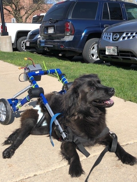
Figure 1. Bronte, Professor Greg Nellis’ dog, in the dog cart.
Design and AM Process Selection
The design decisions surrounding the electronics enclosure including choosing the AM process, material, and dimensions of the box to best suit the intended use of the product. Many goals of the product were related to mechanical properties, such as watertightness, and warpage due to solar exposure/freezing. In choosing the dimensions, the intended fitting method of the mating cover and base of the box was a friction-fit method. This would require the cover to feature very tight dimensions relative to the pre-established size of the base for the electronics, with enough surface area to provide a successful fit via friction. The wall thicknesses of the part were altered in SolidWorks throughout the stages of the project based on the needs of each test. The initially tested materials were chosen with the goal of finding a material that would work similarly to SLA in this regard, with some considerations for weight and cost optimization. It was found that SLA resins would provide high levels of water resistance. However, the costs of this process are very large compared to other processes, such as FFF, which led to the exploration of FFF materials for a watertightness test. The best performer in this analysis would then be utilized when comparing wall thicknesses to finalize the design.
FFF Material Selection
Since we wanted to minimize the cost of the electronics cover, we chose low cost FFF materials available at the Makerspace for our testing [3]. These materials were polylactic acid (PLA), polycarbonate (PC), and nylon. The price of these materials compared to other FFF filament materials is shown in Table 1 below.
Table 1. FFF printed materials chosen for testing with their associated costs [2]. Materials bolded were chosen for testing.
| Material | Cost ($/g) |
| Polylactic acid (PLA) | $0.08 |
| Polycarbonate (PC) | $0.12 |
| Nylon | $0.12 |
| Polypropylene (PP) | $0.13 |
| Polyvinyl alcohol (PVA) | $0.19 |
After selecting to print with these materials, we wanted to perform a single test that would allow us to move forward with a single material. Since the dog cart will be outside and we wanted to optimize for weight, the logical test was to see which material was the most watertight for a given wall thickness, percent infill, and layer thickness.
Material Selection Watertight Test
Procedure
The watertight test looked to observe how the 3 test specimens, made of PLA, polycarbonate, and Nylon, respectively, would allow water to leak through or be absorbed by the part. Each part had equal wall thicknesses of an 8th inch. Each part was weighed to determine the original mass. Three Tupperware containers were then weighed as well, as the parts would be placed in their own container to ensure that any leaked water mass would be measurable. Then, the part was filled to a vertical water level of approximately 3.2 inches. Since masses were considered, any small disparities in the water height were considered negligible as they would be accounted for in the mass calculations. The entire system, comprising of a part filled with water and its respective container, was weighed to determine the mass of the entire system. The parts were then left for approximately 20 hours together in a locker to normalize any evaporation that would occur. After the 20 hours had passed, the total system was then reweighed to determine how much water evaporated. The container was then measured to determine how much water had leaked. Lastly, the part was emptied of its water content and the surfaces were dried prior to reweighing the part to determine if any water had been absorbed into the walls of the materials. Data analysis and collection occurred in Microsoft Excel.
Results
Through visual observation and measuring the entire system, it was found that both the amount of water that evaporated and leaked was negligible and not measurable using a device with a 0.1-gram precision. Thus, it was concluded that at the chosen wall thickness of an 8th inch, all the materials would properly protect against water leakage. However, noticeable differences were observed when considering absorption. The results of the experiment are summarized in table 2 below.
Table 2. Initial and final masses of each box to calculate the absorbed water mass.
| Material | Initial Empty Box Mass [g] | Final Empty Box Mass [g] | Mass absorbed [g] |
| PLA | 118.92 | 118.7 | -0.22 |
| PC | 147.75 | 147.9 | 0.15 |
| Nylon | 118.1 | 132.6 | 14.5 |
It is apparent that with the amount of water absorbed compared to the other two materials, nylon would not be desired for this application as the stored water could lead to eventual leaking and electronic failure, or mechanical failures in the nylon part. Thus, it was no longer considered in this design. Although PLA and PC performed relatively well with respect to absorption (with some errors likely occurring in the PLA measurement, giving a negative absorption value), the PC part featured many external cracks post-processing. Given that many cracks were present, it was concluded that PC would also not be a good candidate for this application as the cracking issue likely stemmed from the material itself. Thus, PLA was chosen to continue further material testing with the intended part geometry while altering the wall thickness to determine final design parameters for this application.
PLA Enclosure Thickness Optimization
After selecting PLA as the best material for the electronics enclosure of the materials tested, we determine how thin the part walls of the enclosure could be while still being watertight. Returning to the initial geometry of the electronics enclosure, we printed two PLA parts with wall thicknesses of 1/16” and 3/32” Reducing the thickness of the walls would decrease the weight of the part. These parts had a geometry that would fit the mating metal part so that the tests results would be a good indication of the actual performance of the final enclosure. These parts were printed at the Makerspace with layer thicknesses of 0.15mm and default infill settings. Once these parts were printed, three tests were performed to determine the suitability of each wall thickness. These tests were a watertight test, UV warpage test, and freezing test.
Watertight Test
The first test we performed with the 1/16” wall thickness part (red) and 3/32” wall thickness part (white) was the watertight test. We wanted to test the watertightness of these parts since they were thinner than the initial PLA part tested which had a wall thickness of 1/8” If the parts leaked or had significant water absorbance, then they would be too thin to be appropriate for the application and a thicker wall thickness would be necessary. The watertightness of the two parts was measured in a similar method as in the material selection watertight test. However, for this test, we gained access to a digital scale to weight the parts and Tupperware which allow our measurements to be more accurate. First, the empty mass of both parts was taken. The parts were filled nearly completely with water and their new mass was recorded. They were then placed in Tupperware containers and were left in the Polymers lab for roughly 20 hours. After 20 hours, the mass of the full parts, empty parts, and Tupperware was taken. Table 3 below shows the results of this watertight test.
Table 3. Results of thickness optimization watertight test.
| Part | Water Evaporated (g) | Water Absorbed (g) | Water Leaked (g) |
| Red Part (1/16” wall thickness) | 18.7 | 0.1 | 0 |
| White Part (3/32” wall thickness) | 20.2 | 0.3 | 0 |
As Table 3 indicates, neither of the parts experienced any water leakage out of the part, and the parts had water absorbance of 0.1g and 0.3g. We believe that these levels of absorbance are acceptable for the electronics enclosure application since the for water to contact and damage the electronics, much more would need to absorb into the walls which is unlikely to happen in normal circumstances. Therefore, based on their watertightness, both the red and white parts would be suitable for the application. Interestingly. both the red and white parts had significant masses of water evaporate out during the test. The values found (18.7 and 20.2) were significantly higher than the mass evaporated in the material selection watertight test. We believe this could be caused by the greater surface area exposed to air in these parts since they have a different geometry as well as the fact that these parts were kept in the Polymers lab rather than a locker.
UV Warpage Test
Because the dog cart, and subsequently, the electronics enclosure would be outside for long periods of time, we wanted to test to see if either of the PLA parts would experience warpage after long exposure to the sun. To test this, the inner dimensions of each part were first measured since those dimensions are most crucial for the 3D printed part and metal mating part to fit. These dimensions were taken at the center of each side since this position had the highest potential for warpage. These dimensions were taken with calipers to achieve the highest precision measurements in order to see any small changes after the test was complete. These dimensions are shown in Table 4. After measuring the initial dimensions, the parts were placed next to each other outside on a sunny day and were left for ten hours. This experimental setup is shown in Figure 2 below.

Figure 2. PLA enclosures left in the sun.
After ten hours had passed, the inner dimensions of the parts were measured again. The initial, final, change, and percent change in inner lengths and widths measured are shown in Table 4.
Table 4. Initial, final, change, and percent change in enclosure inner dimensions for UV warpage test.
| Dimension | Initial (in.) | Final (in.) | Change (in.) | Percent Change (%) |
| Red Part Inside Length | 4.550 | 4.575 | 0.020 | 0.44% |
| Red Part Inside Width | 3.577 | 3.582 | 0.005 | 0.14% |
| White Part Inside Length | 4.570 | 4.532 | -0.038 | -0.83% |
| White Part Inside Width | 3.580 | 3.538 | -0.042 | -1.17% |
As the data in Table 4 shows, there was minimal measured warpage in the red part with slightly more warpage in the white part. It is important to note however, that the measured differences could be caused by measurement error rather than true changes in dimension since it was difficult to keep the calipers perfectly aligned when measuring the middle of the part. This test indicates that the thinner (1/16” wall thickness) part would be able to withstand extended periods in the sun without warping better than the thicker (1/8” wall thickness) part. This means the thinner part would also be less likely to crack due to stresses caused by warpage while it fit on the mating metal part. Though the results show that the thinner red part is more resistant to warping due to UV exposure, we were not able to draw concrete conclusions from this test due to the high estimated measurement uncertainty.
Freezing Test
To simulate the effects of experiencing extreme weather, the parts were put through a designed freezing test. The goal of this test was to analyze the watertight properties under colder temperatures. To run this test, water was filled up to a marked line in the parts and both parts were placed in the freezer. This test setup can be seen in Figure 3.
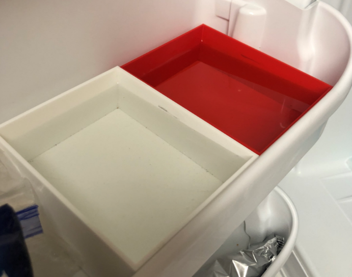
Figure 3. Freezer test setup
The parts were kept in the freezer for 16 hours to allow for the water to freeze and the part to experience the full effect of the freezing. At the end of the 16 hours, the parts were taken out of the freezer and inspected. In Figure 4 you can see that one part had created a major crack that resulted in extreme leakage upon the ice melting.
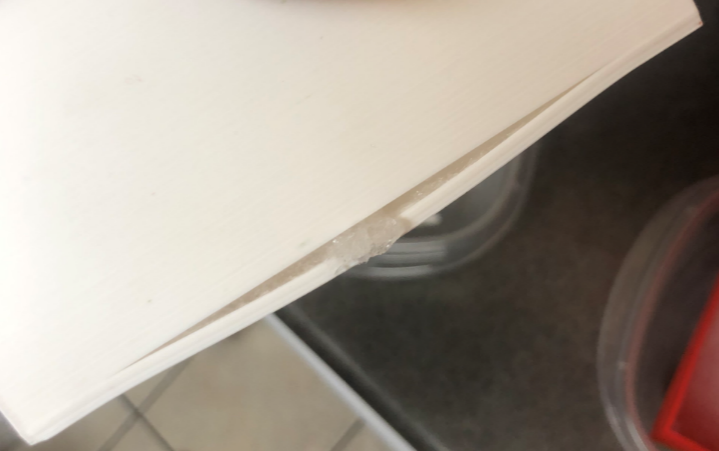
Figure 4. A crack in the thick part from the freezing test.
Even with this observation, a similar watertight test was completed for both tests. The parts were placed in their respective Tupperware containers and left in a room at room temperature for 24 hours. This allowed the ice to melt, and the parts could express their watertight properties after experiencing long-term frozen temperatures. The results of this test are shown in Table 5.
Table 5. Freezer test numerical results
| Part Specifications | Percent of Water Leaked | Mass of water Absorbed |
| Red Part (1/16” wall thickness) | 3.364% | 0.4 [g] |
| White Part (3/32” wall thickness) | 100% | 0.4 [g] |
Based on these results, it is fair to say that under the more extreme weather cases, the parts will absorb slightly more water. Along with that, since cracks did form in the part with a larger thickness, it is fair to conclude that the larger the diameter, the more rigid the part, and the less formability it will have when exposed to more extreme weather situations. Although we did measure some leakage in the red part, some error could be assumed due to condensation that was observed when the part was in the melting phase of testing. This final test provided great insight on the watertightness of PLA under different conditions.
Results & Discussion
After performing many watertight tests with FFF printed parts, a PLA printed part with 1/16” walls would be the best option when creating a part that needs to be watertight, cheap, and easy to use. After first deciding that PLA would be the most efficient material for this application, further tests were performed to optimize the thickness and cost of a PLA printed part. With the 1/16” thick part, it showed good watertight properties during the simple watertight tests. When further testing the parts under UV rays in the sun, the 1/16” thick part saw less warpage than the 3/32” thick part. Along with that, the 1/16” thick part did not crack when exposed to the frozen water in the freezing test. This could be because of the greater flexibility of this part over the 3/32” thick part. Since the thinner part was able to withstand a simple watertight test, a UV test, and freezer test, it was determined to be the best part for this application.
Conclusions
Watertightness in additive manufacturing parts is a very important characteristic in many products. With the known exceptional watertight properties of SLA printed parts, we wanted to see if a cheaper process like FFF could simulate these watertight properties. After many watertight tests with FFF parts of PLA, PC, and Nylon, we were able to create very good, watertight parts that could be used in applications exposed to water. For the given application, this a FFF printed part with PLA would be able to house the electronics necessary on Bronte’s dog cart.
References
[1] Xometry, Will It Leak? 3D Printing Watertightness Test. 2016.
[2] “3D Printer Material Cost: The Real Cost,” All3DP, Sep. 08, 2020. https://all3dp.com/2/3d-printer-material-cost-the-real-cost-of-3d-printing-materials/ (accessed May 05, 2021).
[3] “Make a Reservation to purchase from the Mini-Mart,” UW Makerspace. https://making.engr.wisc.edu/mini-mart/ (accessed May 05, 2021).