Abstract
Consumer products can be successfully manufactured using additive techniques when appropriate design considerations, material selection, and market research are utilized. In this study, two 3D-printed designs for a passive phone amplifier, named “Amplifi3D,” were evaluated based on their amplification ability, acoustic quality, print and aesthetic quality, usability, and durability. Both were printed with polylactic acid (PLA) using the FFF (Fused Filament Fabrication) additive manufacturing techniques based on print time and design constraints. The resulting prints demonstrated functionality in terms of ability to amplify sound, maintain sound quality, and structurally withstand drops. Ultimately, the “Amplifi3D V2” design outperformed the “Amplifi3D V1” design in all of the aforementioned testing categories. Thus, the group presents the “Amplifi3D V2” passive amplifier as a stylish, cost effective, and convenient way to amplify built-in phone speakers, and demonstrates the design freedoms 3D printing provides.
Introduction
Background
Passive amplifiers are devices that amplify sound without the use of power. Utilizing 3D printing, the aesthetics can be customized, and the shape can be small and lightweight for travel purposes. This is also inexpensive to create, and is convenient due to the lack of battery charging. Working off the same acoustic principles as musical instruments, a passive speaker amplifies sound by changing the impedance of the air around the speaker to maximize the efficiency of your music player.
Built-in phone speakers are generally designed for speech quality as opposed to music quality. Generally, they have poor frequency response and low power due to their small size and lack of proper resonance chambers to boost bass. Passive amplifiers that interact with mobile devices are designed such that ideal frequency response, sound amplification, and sound quality are achieved. These passive amplifiers act as resonators driven by the built-in speakers of the phone. The flexibility of 3D-printed designs with additive manufacturing techniques allows designers to precisely tailor sound amplification, sound quality, and ultimately resonance response of passive amplification devices based on the device shape [1].
Passive amplifiers are widely available on the market, come in a variety of geometries and materials, and are manufactured using various methods. The first product to look at is the “Speakaboo” which derives its name based on the shape of the bamboo branch it is made from. This speaker allows a user to charge their device while it is docked, but this requires the user to meticulously thread their charger through the “bamboo” branch. A more complex product made by Restoration HardwareTM called the “Gramophone” takes its inspiration from the phonograph in creating its passive amplifier [2]. The classic looking design holds the phone in a wooden base and directs the sound in channels up to an iron and brass horn. It is aesthetically appealing and able to boost the volume from the speaker by 3-4 times [4]. The design does have significant drawbacks though since it is limited to iPhone models, does not have space for a charger, and its odd shape and large size makes it hard to travel with. Lastly, “The Horn Stand” uses a silicon mesh to fit around the base of the phone to provide amplification [3]. The sound is focused through a channel into a horn providing amplification of 13 decibels while allowing room for a charging cable [4]. The design is limited to a specific generation of the iPhone which limits its versatility between not only other brands but also within iPhone models specifically. Examples of these current models are shown below in Figure 1.

Figure 1. Passive phone amplifier products “Speakaboo” (left) [2], “Gramophone” (middle) [3], and “The Horn Stand” (right) [4].
Print Designs
The goals the team identified and prioritized in the print trials for the 3D printed passive phone amplifier are based on research of acoustics and current models, as well as personal preferences. These are described in Table 1 below.
Table 1. Design goals and significance, rated on a scale from 1 (least) to 5 (most).
| Goal | Significance |
| Amplifies the phone speaker’s sound by at least 10 dB without power | 5 |
| Retains or improves the phone speaker’s sound quality | 5 |
| Stays under the 8 hour print time and cost limit for the project | 5 |
| Allows easy placement and removal of the phone | 4 |
| Provides a way to charge the phone while the amplifier is being used | 4 |
| Securely holds and works with the most popular models of the iPhone and Android | 3 |
| Survives drops/falls up to 4 feet | 3 |
| Fits and stays in place in small spaces (< 100 in3) | 2 |
| Functions for at least 500 hours of use | 1 |
| Works in indoor and outdoor settings | 1 |
To accomplish these goals, the team printed two designs, each with their own iterations to make minor adjustments. The first design is shown below in Figure 2 and will be referred to as “Amplifi3D V1” or “V1”. As shown, this design holds the phone in a horizontal orientation. This allows the user to watch videos while using the amplifier and provides routing for the charging cable to the side of the product rather than the bottom. This print took 8 hours and 11 minutes, used 10% infill, and its dimensions were 197 x 89 x 37 mm (W x H x D).

Figure 2. Solidworks model (left) and printed model (right) of the first passive phone amplifier design, Amplifi3D V1.
The second design is shown below in Figure 3 and will be referred to as “Amplifi3D V2”. This second design rotates the phone to an upright position, primarily to lower the overall size of the product. This design holds the phone securely and has a more direct sound channel. This print took 8 hours, used 10% infill, and its dimensions were 100 x 100 x 50 mm (W x H x D).

Figure 3. Solidworks model (left) and printed model (right) of the second passive phone amplifier design, Amplifi3D V2.
This work will focus on describing the methodologies used for these two designs, as well as comparing the designs to each other and to common amplifying devices based on acoustic amplification, acoustic quality, print and aesthetic quality, usability, and durability.
Methodology
Material Properties
The primary consideration for selecting a material was acoustic amplification, and the secondary consideration was structural stability. This necessitated evaluating material density, elasticity, stiffness, wall-thickness, geometry, and percent in-fill of the 3D printed part. Acoustics research showed that the highest acoustically performing materials have a low density, high elasticity, and high stiffness [5].
Thermoplastics used by the Ultimaker FFF printer and thermosets used by the FormLabs SLA printer were assessed for the print, as this is what was available at the UW Makerspace. The materials with the most promising properties were the Formlabs “Tough Resin” and “Rigid Resin”. The material choices were evaluated based on their densities, elasticities, stiffness, and the speed of sound in the material. Elasticity is measured by the elastic modulus, stiffness is proportional to the elastic modulus, and the speed of sound in a material (C) is given by Equation 1.
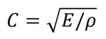 Equation 1
The in-fill density was chosen on the basis of the minimum density at which it can maintain structural integrity under the normal wear and tear of phone placement. After the first print was deemed structurally sound by the drop test and multiple phone placements, the 10% infill density was also used in subsequent prints. The walls of the passive speaker needed to be thick enough that they would perfectly reflect the sound, and also be able to absorb the impacts of phone placement without deforming. It was thus decided that the walls would have a thickness of at least 2 mm.
Additive Manufacturing
The additive manufacturing process used throughout this design was Fused Filament Fabrication (FFF). Stereolithography (SLA) was also considered, and in terms of acoustic qualities of the material, would have been preferred, but the team ran into problems supplying a suitable model for SLA printing, and predicted print times were exceeding the 8 hour limit. The first problem with SLA the team encountered was that the maximum SLA print size is much smaller than the FFF maximum print size, and the first model was over the maximum size for any SLA printer at the UW Makerspace. Formlabs Form 3 (SLA) bed size is only 185 mm (z-axis – maximum), while the Ultimaker S5 (FFF) that was used has a bed size of 330x240x300 mm, which was an acceptable size for the early iterations of the model.
The second problem encountered is related to the first, and was the limitation on print time. Using “Formlabs Draft” resin with one of the early design iterations for an SLA print estimated a time of ~7 hours, but the print quality would have suffered due to the nature of that resin. Every “standard” print resin used with the SLA printers estimated print times in excess of 15 hours. Comparatively, using a FFF printer the print time was ~8 hours, using standard 0.2mm layer height and medium quality.
After printing and testing Amplifi3D V1 model, the Amplifi3D V2 model implemented key changes which reduced the size of the print so that it fit on the bed of an SLA printer and the print time was acceptable. However, when slicing the model with PreForm to print using an SLA printer, the UW-Madison Makerspace informed the team that the support structure needed for such a print would be incompatible with SLA printing techniques, and that FFF was a ultimately a much better option in terms of print geometry.
Analysis & Results
Acoustic Amplification
Decibel measurements were made to asses acoustic amplification for the following four chosen audio devices:
- Built-in speakers on the Google Pixel 4a (baseline measurements)
- Amplifi3D Design
- Plastic Cup
- Bose Micro Bluetooth Speaker
For consistency in testing, the same audio clip was used for all experiments. A pure 432 Hz note audio clip was played continuously such that the measured decibel level was a function of the amplification, and not the changing frequency of the audio clip itself. The decibel level was recorded over a 10 second interval and the average dB over this time period was used as the metric. The iOS “Decibel X” application was used to make all decibel measurements. An iphone 12 Pro with the “Decibel X” application open and recording was placed 1 foot in front of each of the audio devices to take the decibel level measurements. Figure 4 below shows the testing setup.
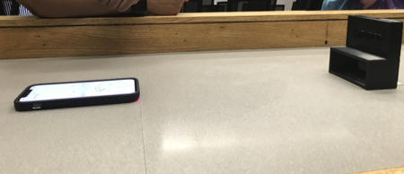
Figure 4. Example of the testing setup for the Amplifi3D passive amplifier. 1 foot of distance was measured between the decibel meter on the phone and the amplifier (V2 pictured here).
Results from the acoustic amplification testing are summarized below in Figures 5-7. Overall, the Bluetooth speaker performed best in amplification ability. In the initial testing results, the Amplifi3D V1 design performed more poorly than both the plastic cup and the Bluetooth speaker at the 50% and 100% volume ranges respectively and performed comparably to the plastic cup at the 25% volume range. Amplification measurements for the second redesigned print, Amplifi3D V2, showed improvement in amplification ability, outperforming the V1 design at all three volume ranges (25%, 50%, and 100%) by 4%, 1.6% and 0.9% respectively. The “Amplifi3D V2” also performed appreciably better than the plastic cup at the 25% and 100% volume ranges. However, at the 50% volume range, the plastic cup outperformed the V2 design. It is suspected that the cup at 50% datapoint is artificially high due to errors in data collection. Future work should involve repeating baseline and dB readings for more accurate measurements.

Figure 5. Comparing % dB increase of both print designs to a plastic cup and Bluetooth speaker at 25% phone speaker volume range.
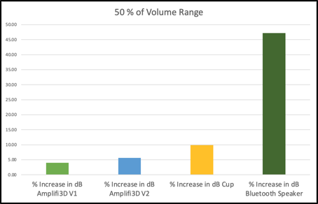
Figure 6. Comparing % dB increase of both print designs to a plastic cup and Bluetooth speaker at 50% phone speaker volume range.
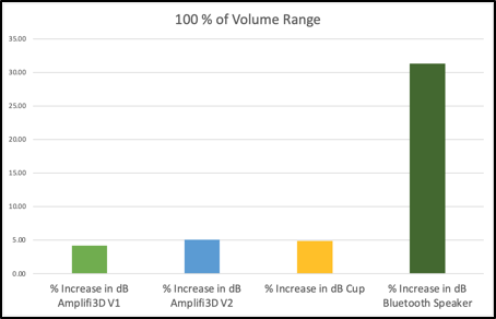
Figure 7. Comparing % dB increase of both print designs to a plastic cup and Bluetooth speaker at 100% phone speaker volume range.
Several of the redesign considerations for the “Amplifi3d V2” involved improving the amplification ability of the device from the first print. Namely the size, number, and shape of the amplification channels were modified to produce better amplification results. In terms of acoustic amplification, the redesigned “Amplifi3D V2” performed better than the “Amplifi3D V1” across all data points, which is summarized in Table 2.
Table 2. Performance of both print models based on % increase compared to the phone built-in speaker, along with the improvement between the first and second iterations.
| Volume Range | % Increase in dB | ||
| Amplifi3D V1 | Amplifi3D V2 | V2 – V1 | |
| 25% | 5.56 | 9.58 | 4.02 |
| 50% | 4.04 | 5.66 | 1.62 |
| 100% | 4.16 | 5.07 | 0.91 |
Acoustic Quality
The acoustic quality test consisted of each group member listening to a pop song by the group Passion Pit through each of these audio devices: the Google Pixel with its built-in speaker only, the Google Pixel placed inside a plastic cup, the Google Pixel paired to a Bose Micro Bluetooth speaker, and the Google Pixel placed in the Amplifi3D design. Each group member then rated the acoustic quality of each device on a scale from 1 to 10, with 10 being the “best” acoustic quality.
Results from both the initial V1 testing and secondary V2 testing are presented below in Figure 8. Design improvements from V1 to V2 resulted in a ~20 % increase in acoustic quality, as the V2 design allowed for better sound transmission from the phone to passive speaker. Although the V1 design was able to outperform the plastic cup and the phone built-in speaker in sound quality during initial testing, it was unable to surpass the Bose micro Bluetooth speaker. V2 however, did outperform the Bose micro Bluetooth speaker in sound quality, solidifying its place as the acoustic device with the best acoustic quality.
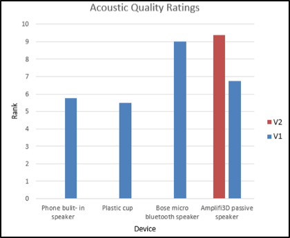
Figure 8. Average results of acoustic quality ratings for each audio device. V2 ranked the highest on average.
Print Quality and Design Aesthetics
The print quality and design aesthetics test consisted of each group member inspecting the Amplifi3D design and rating its aesthetic quality and other practical criteria. Each member rated the product based on criterion shown in Table 3 below, on a scale from 1 to 10.
Table 3. List of criteria used to evaluate the print quality and design aesthetics of the Amplifi3D design.
| 1 | Free from major print defects |
| 2 | Free from minor print defects |
| 3 | Size is suitable for use in home |
| 4 | Design aesthetic is pleasing |
| 5 | Free from sharp edges |
| 6 | Free from this sections prone to breaking |
The graph displayed in Figure 9 compares the qualitative performance between V1 and V2. Amplifi3D V2 showed improved performance in all categories except category 5 (free from sharp edges). This may be due to the more rectangular, block-shape design of the V2 design vs. the more filleted curve design in V1. V2 improved the most in category 1 (free from major print defects). This was likely due to the design and color of the new print, as its black, blocky frame was able to better conceal any imperfections. The FFF printer also appears to have printed the Amplif3D V2 design with overall higher quality than the first, as notable improvement is seen in the “free from minor print defects” category. Overall, the Amplif3D V2 print improved in criterion from V1, especially in print quality.
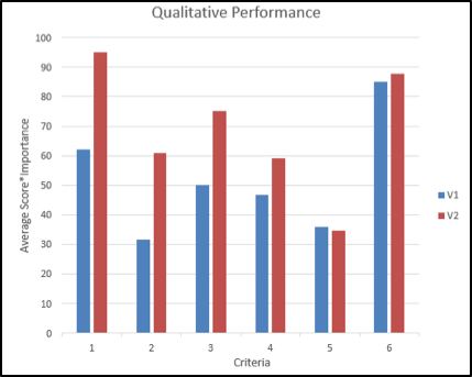
Figure 9. Qualitative performance of the Amplifi3D designs based on the identified criteria. Each individual’s (score* importance) is plotted against the criteria number for each version (V1 and V2) of the prints.
Usability
The usability test measured how easily one is able to insert, hold, and charge the phone while using the passive phone amplifier. Each team member scored each of these criteria on a scale from 1 to 10.
The results between the two models for usability are shown in Table 4 below. The V2 design holds the phone more securely than the V1 because it has a slot dedicated for the phone opposed to a ledge the phone rests on. The slot is dimensioned to fit a phone that is 80 mm wide, 10 mm thick, and 180 mm tall. A drawback is that the phone needs to be removed from its case for some phone models, making it harder to insert and remove the phone. The charging cable was easier to use in the V2 model since the cable didn’t have to be woven through the amplifier, but this could still be improved.
Table 4. The results of the usability testing for the design based on the average team member’s rankings of each of the three criteria.
| Criteria | V1 Average Score | V2 Average Score |
| Ease of phone insertion and removal | 9 | 7 |
| How securely the phone is held/stays in place | 5 | 7.1 |
| Ease of using charging cable while phone is installed | 4.5 | 5.6 |
Drop Test
The drop test was a simple measure to ensure the print had enough infill support to prevent breaking or damage if it were to fall off of a surface. For both designs this was not an issue and they were able to be dropped from 4 feet repeatedly without any damage.
Discussion
Design comparison
From the results of the five tests performed, it was shown that the Amplifi3D V1 successfully passed most of the testing criterion and that Amplifi3D V2 improved upon V1 in most tests. V2 increased the level of acoustic amplification from V1, but still did not reach the goal of a 10 dB increase. However, V2 greatly outperformed V1 and even the Bluetooth speaker in acoustic quality. Additionally, the print quality and aesthetics of V2 were rated very high, much more so than V1. The V2 model made it less easy to insert and remove the phone than the V1 model, but it held the phone more securely and made it easier to use the charging cable. Finally, both designs were deemed sufficiently durable as neither were damaged during the drop test.
The iteration process following the first design looked at the test results for manageable changes to the design to allow it to meet requirements and improve the performance. The three critical aspects addressed between the two designs were the sound flow path, the phone orientations, and the model footprint.
The V1 model did not reach the sound amplification goal. Through inspection of the part, it was determined that the sound amplification flow path was not easy for the phone speaker to line up with. This was in part due to the sideways design with sharp corners as well as the inclusion of the charging cable. Conversely, the V2 design smoothly connected the speaker from the phone directly to the audio channel. It also retained the charging cable slot, which was a critical aspect of the design.
This adjustment of the sound flow paths and charging cable inclusion required the phone to be oriented vertically in V2. In order to do this, the phone slot was designed based on the popular phone models sold in the United States including iPhone, Samsung, and Google. The vertical orientation required less of a footprint on a print bed. This was important to address because the first model was too large for FormLabs Stereolithography (SLA) printers available to use.
Conclusion & Outlook
The team had two main print designs for the passive phone amplifier. The first design, the Amplifi3D V1, moderately achieved the team’s goals, and the second design Amplifi3D V2 improved in several key areas. The final model met the team’s goals of improving sound quality, staying under the 8 hour print time limit, securely holding all popular phone models, surviving repeated drops, and fitting in small spaces/ being a suitable size for home usage. Improvements to be made in future iterations would include the goals of increasing the dB amplification to 10 dB, simplifying the placement and removal of the phone, and simplifying the charging mechanism.
Additional testing needs to be performed to measure the goals of the amplifier working indoors and outdoors, and the amplifier working for at least 500 hours of use as these were not able to be performed due to time constraints. Also, when testing future iterations, baseline measurements should be repeated before each measurement to improve their accuracy.
Future Iterations
Future iterations should aim at improving the device’s amplification, fixing defects, and improving the usability of the device. These improvements should be made while also retaining the high acoustic quality and durability the current V2 model demonstrated.
It would be ideal for future prints to use an SLA printer because of its superior quality in printing, which will create better acoustics. Specifically, this should improve the amplification ability and sound quality of the passive amplifier. The design should avoid using internal passages as they do not translate to the SLA method. The first iteration, Amplifi3D V1, avoided large internal passages, but it was too large for an SLA printer. It also was not extremely effective at amplifying quality sound, so the second iteration, Amplifi3D V2, used supports and internal passages to create more direct sound passages. Unfortunately, based on the angled orientation of these, this second design also was unable to use SLA printers. A future design should avoid internal passages and be small enough to be printed on an SLA printer, but still retain acoustic ability.
There are a few minor print defects on the final print that do not affect the performance of the product, but could be improved upon. First, on the inside of the cavity where the phone is placed, the surface finish is rough where long bridging was required, even with supports. Second, the edges of the backside have some small pieces of the filament raft that was required to hold the print to the bed while printing. Finally, the surface finish of the back (that was on the print bed) is considerably shinier and has an uneven appearance compared to the rest of the print. These should be improved in future iterations.
The V1 model made it easier to place and remove the phone than the final V2 model, and it showed the entire phone screen. However, the V2 model held the phone more securely and made the charging cable slightly easier to use. A future iteration should work to combine the positive aspects from each of these models. Therefore, a possible iteration could adjust the vertical support design so that the phone is easier to place and remove, and the whole screen is visible and usable, but still holds the phone securely. It could also include an angled back support to provide more support for holding the phone. Additionally, it could include a larger opening and resting size for the charger as this was an issue with the V2 model, but still retain the direct connection between the audio channel and phone speaker. These changes would prevent the user from having to remove their phone case, and make it easier to use and charge.
A possible example for a future iteration that combines these changes is shown below in Figure 10.
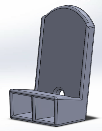
Figure 10. Future iteration considerations design.
References
- T. Lokki, S. Serafin, M. Müller, and V. Välimäki, Sound and Music Computing. MDPI, 2018.
- “Acoustic iPhone Speaker Bambo (Page 1) – Line.17QQ.com.” https://line.17qq.com/articles/ecerewcqx.html (accessed May 05, 2021).
- “prod2320166 (650×634).” https://media.restorationhardware.com/is/image/rhis/prod2320166?$PD$&illum=0 (accessed May 05, 2021).
- “308b06b08b5e9312b456d344aa394b5c.png (414×460).” https://i.pinimg.com/originals/30/8b/06/308b06b08b5e9312b456d344aa394b5c.png (accessed May 05, 2021).
- “Which Materials Carry Sound Waves Best?” https://sciencing.com/materials-carry-sound-waves-8342053.html (accessed May 05, 2021).
- “3D Printing Materials for Professionals,” Formlabs. https://formlabs.com/materials/standard/ (accessed May 05, 2021).
- “Minimum Wall Thickness for 3D Printing,” Formlabs. https://formlabs.com/blog/minimum-wall-thickness-3d-printing/ (accessed May 05, 2021).
- “The widest material choice on the market | Ultimaker,” ultimaker.com. https://ultimaker.com/materials (accessed May 05, 2021).