Abstract
Fused Filament Fabrication (FFF) is among the most popular additive manufacturing (AM) technologies available. Materials used in FFF are primarily polymers, low melting temperature metal alloys, and even composite materials. Studies have been performed to determine the mechanical properties of components fabricated by FFF. It has been observed that structural parameters such as filament separation, printing orientation, and material layers have a great influence on the mechanical properties of FFF components. This highlights the importance of understanding the structure-property relation in parts fabricated using this AM technology. Building on past works, it is of interest to determine the effect of varying part layer height and number on the longitudinal (Xt) and transverse (Yt) tensile strength. Natural polylactic acid was used to craft rectangular tensile testing bars of variable layer height. These bars were made with two different print orientations (parallel and perpendicular to the loading direction). By varying the effect of the number of layers at a fixed standard sample height, it is possible to identify the critical layer number, which identifies the point at which the mechanical properties of the proposed part do not change, regardless of the number of layers that are added. This revealed a trend in which an increase in layer height led to a drastic decrease in material properties and an increase in rejected samples and sample defects.
Introduction
Fused form fabrication (FFF, also known as fused deposition modeling, FDM) is the process of printing structures in a layer-by-layer fashion via extrusion of a polymer filament through a heated nozzle, generally conducted by using simple non-reactive thermoplastics. A 3-dimensional structure is first drafted in CAD and then deconstructed into a series of 2D slices, which are printed layer-by-layer via the movement of the extrusion nozzle in the x-y plane (Figure 1). The build platform (or the extrusion nozzle) moves along the z-axis to allow the nozzle to print multiple layers sequentially. The melted polymer undergoes thermal fusion with the underlying structure and solidifies upon cooling to form a permanently bonded structure. Compared to other AM techniques, parts printed by FFF are more suitable for demanding applications where high strength and thermal resistance are necessary since the wide range of thermoplastics that are amenable to FFF encompasses materials with good mechanical properties.
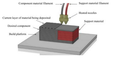
Figure 1. Illustration of FFF process.2
Compared to traditional manufacturing methods for polymeric materials such as injection molding, thermoforming, and extrusion, additive manufacturing represents a fundamentally different approach whereby individual layers are deposited sequentially to build up a 3-dimensional structure.2 This allows the production of complex geometries that are not easily attainable via subtractive manufacturing techniques. Additive manufacturing is particularly advantageous for small batch size production and developmental activities since tooling and long lead times are eliminated in the manufacturing process.
While additive manufacturing has generated excitement across many fields, there are several challenges that have limited commercial utilization of AM technology. Importantly, additive manufacturing is inherently slower than conventional manufacturing processes since parts are built one at a time. This means that AM, in general, cannot compete with traditional methods for large-scale manufacturing. Another problem facing AM has to do with the resolution of printed lines, often limited to a minimum width of ~100 µm. This leads to parts with much higher surface roughness compared to injection molded or milled plastics. Furthermore, the accuracy of printed parts can deviate significantly with respect to their computer drafted models due to instabilities in the printing process and because of post-deposition cooling and/or shrinkage that results from complex cure processes. More importantly, the layer-by-layer approach that is used in most AM methods can generate ‘weak links’ between lines, which may result in significant loss of overall mechanical properties such as toughness. This also leads to difficulty in predicting the mechanical properties of 3D printed parts since the strength of the material is intimately related to the printing parameters (i.e., print direction and any cure on-demand features).
Comparing the bulk mechanical properties to those of FFF printed parts reveals that printed parts generally have lower performance compared to the bulk material. This is expected since the thermal fusion bonding process that occurs during FFF leads to parts with relatively weak connections between layers and generates a final structure with internal porosity. In some cases, the difference in mechanical properties is very large, particularly for maximum elongation at break. For the most part, the polymers maintain the same rank in mechanical properties regardless of whether they are printed or measured in bulk. Thus, while the FFF process generally leads to weaker structures compared to bulk processing, the intrinsic properties of the polymer are still the limiting factor affecting the overall strength of printed structures. It is important to recognize that structures fabricated using FFF are also heterogeneous with respect to the printed filament geometry, which in turn leads to heterogeneous or anisotropic mechanical properties. The choice of print direction is therefore critical for achieving optimal performance of parts printed using FFF.
With the growing application of 3D printing technologies, many polymer materials are being used for additive manufacturing.3 Polylactic acid (PLA) is one of the most widely used polymers in 3D printing technologies. PLA is a biodegradable aliphatic polyester derived from lactic acid, extracted from sugar, cassava, corn starch, etc. PLA has excellent properties such as high strength and hardness, renewability, and low toxicity. However, certain properties of PLA, such as brittleness, low heat deflection temperature, poor crystallization, and narrow processing range, limit its application.
To validate the mechanical properties and functionality of a printed part, it is necessary for the material properties to be studied in conjunction with the printing parameters.4 It is crucial to understand the relationship between mechanical properties and printing parameter combinations so that a bridge to optimized information on mechanical properties can be formulated. The strength of FFF parts is primarily dependent on printing parameters, such as layer height, raster angle, and infill density. The layer height refers to the height of the z-axis motion of the extruder during the printing process and directly reflects the thickness of the deposited layer. This value cannot be larger than the nozzle diameter. The raster angle is the angle or direction of the material about the loading of the part. The infill density refers to the amount of deposited material on each surface layer and directly affects part strength, print time, and material amount.
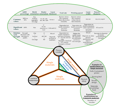
Figure 2. Summary of FFF materials and corresponding process factors.5
Materials and Methods
An Ultimaker 3 Extended dual extrusion 3D printer with 0.4 mm nozzle diameter was used to fabricate the tensile test specimen using 2.85 mm MatterHackers Natural Translucent PLA 3D printing filament. CAD was used to create the model for the tensile test piece. Cura was used as the slicing software to generate the G-code files to be inserted as the command-and-control language of the 3D printer to carry out the printing process. Figure 3 shows the model of the test piece, while Table 1 holds the nominal values for the printed parts. The samples were constructed following the ASTM specifications for a Type I tensile specimen (ASTM D638)6. Table 2 contains the constant printing parameters kept between samples, and Table 3 holds the various sample designations.
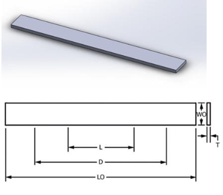
Figure 3. Simple tensile test piece model (left) and dimensions of the test piece (right).
Table 1. Nominal values for the FFF part dimensions.
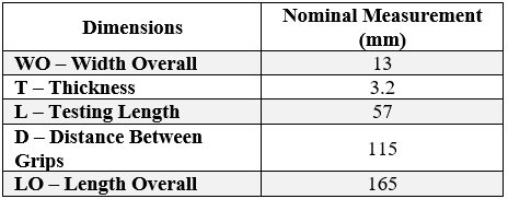
Table 2. Printing parameters that were kept constant.
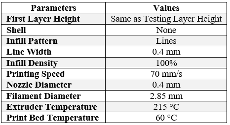
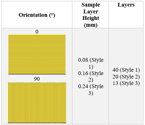
Table 3. Experiment sample designation.
An Instron Universal Testing Machine with metal grips equipped for tensile testing and a 20 kN load cell was used for testing. To enhance contact between the grips and the sample, emery cloth was placed between the sample and grip, ensuring contact and increasing friction. A test speed of 3 mm/min was employed for all samples. An Instron extensometer was utilized to capture the stress-strain measurements.
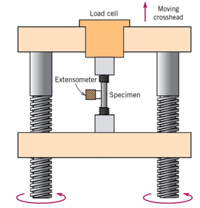
Figure 4. Schematic representation of tensile testing setup
Prototype Takeaways
There were some key takeaways from the prototyping. First prints which were printed in the MakerSpace had defects in them such as gap in beads and irregular surface finish as shown in the figure below. Despite tweaking print parameters, best possible print could not be achieved. Upon analysis it was observed that incorrect part dimension could be one possibility. Additionally, there was a limitation of printing at MakerSpace as maximum nozzle diameter available was 0.2mm against our planned requirements of up to 0.4mm. Fresh prints were printed in Polymer Engineering Center (PEC) and prints were found out to be acceptable.
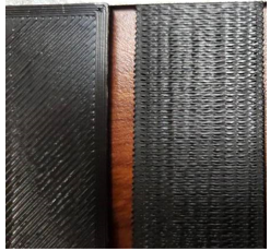
Figure 5. First prints with defects.
Further printing Style 4 and 5 turned futile as there was under extrusion and one such explanation is that print diameter (0.32mm) was close to the nozzle diameter of 0.4mm and hence it was decided to keep Style 4 & 5 for future work.
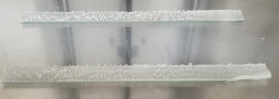
Figure 6. Style 4 printing (under extrusion).
Results and Discussion
Specimen Dimensions
While not the focus of this report, each specimen was measured for its width and thickness for how well they conformed to the nominal dimensions outlined in ASTM D638. Measurements demonstrate that both width and thickness tended to decrease as layer height increased, shown in Figure 5 and Figure 6. In addition, the width tended to be 0.5 mm larger for specimens with This is related to the release of internal stresses in the direction of print, along with thermal shrinkage and expansion effects.
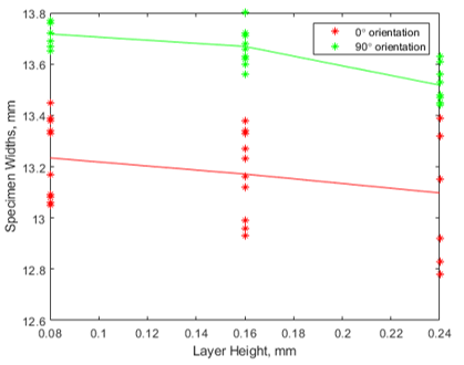
Figure 6. Specimen width vs. layer height. Trend demonstrates a decrease with layer height.
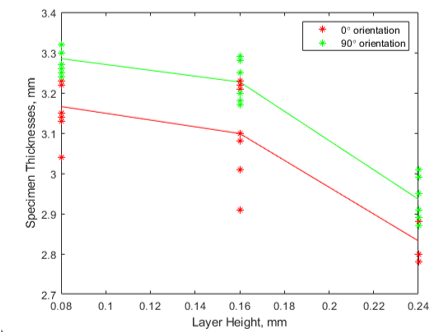
Figure 7. Specimen thickness vs. layer height. Trend demonstrates a decrease with layer height.
Tensile Modulus
The experiments demonstrate that tensile modulus decreased as layer height increased, shown in Figure 7. The behavior is expected since increasing layer height is equivalent to lower fill resolution in the print. Lower print resolution means larger faults in the specimen, resulting in lower tensile modulus.
In addition, the tensile modulus was 1850 MPa to 1610 MPa larger for fill specimens than fill specimens. The fact that fill specimens had higher tensile modulus is expected since the filament is parallel to the loading. The filament orientation grants the fill specimens greater ability to carry the load. On the other hand, for specimens with fill, the filament is printed perpendicular to the load. As a result, only the binding between layers can resist the load.
The tensile moduli are summarized in Table 4. The tensile modulus tends to decrease with layer height and is greater for fill orientation. These are calculated from raw data shown in Appendix A. The tensile moduli match corresponding stress-strain data when the two are plotted together in Appendix B.
Table 4. Tensile modulus results with respect to specimen configuration.
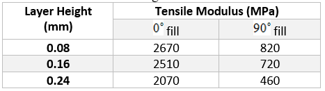
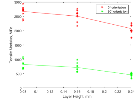
Figure 8. Tensile modulus with respect to layer height.
Tensile Strength
Like with tensile modulus, the tensile strength tended to decrease with increasing layer height for fill specimens. As before, this behavior can be explained with lower resolution in the print, resulting in larger faults and decreased ability to bear the load. However, the tensile strength for This may be due to our samples being above the critical layer number, which means that the mechanical properties would see little to no change. There is weak evidence suggesting that tensile strength increased from 0.08 mm to 0.16 mm layer height and decreased afterward, which may suggest a maximum for tensile strength.
Similarly, tensile strength tended to be larger for fill specimens than fill specimens, as seen in Figure 8. Following the same reasoning as with tensile modulus, this behavior occurs since filaments oriented parallel to the load are better able to resist said load than filaments oriented perpendicular to the load.
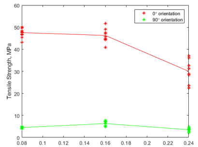
Figure 9. Tensile strength with respect to layer height.
Tensile Elongation
As with tensile modulus and tensile strength, fill specimen elongation at fracture tended to decrease with layer height. The fill orientation explains this trend as well since the filament was printed parallel to the load. As with tensile strength, the tensile elongation deviated from the expected behavior for fill specimens. Instead, the elongation in these specimens increased, then decreased. The appearance of an elongation maximum follows similar behavior in tensile strength but is much easier to see in tensile elongation. As expected, tensile elongation tended to be larger for fill specimens than fill specimens. The difference can be explained in terms of filament orientation in the same way as tensile modulus and tensile elongation.
Conclusions
Measurements showed that the tensile modulus, tensile strength, and tensile elongation all decreased with increasing layer height for fill specimens. While the tensile modulus also decreases with layer height for fill specimens; the same cannot be said for tensile strength or tensile elongation. In fact, the latter two appear to stay the same or reach a maximum at 0.16 mm. Barring the last two exceptions, tensile modulus, tensile strength, and tensile modulus decreased with layer height, reflecting the increased effect of faults in lower resolution prints.
In addition, this report found that the tensile moduli for the specimens decreased from 2670 MPa to 2070 MPa for fill specimens and decreased from 820 MPa to 460 MPa for fill specimens as layer height increased from 0.08 mm to 0.24 mm. In all cases, the fill specimens had greater tensile modulus, tensile strength, and tensile elongation than their fill counterparts. This is expected since filaments oriented parallel to the loading direction can better resist the load. Filaments oriented perpendicular to the load mean that only the binding between layers can carry the load.1,2,11–17,3–10
Future Work
Many different adaptations and tests have been left to the future due to lack of time and technical issues. For starters, future work will entail printing and testing of Style 4 samples after failure to do so for the initial timeframe. Furthermore, samples have demonstrated few internal defects and voids. One solution to the problem is the use of a different slicing software, SciSlice, than the one used for the initial project (Cura). The gcode generated by SciSlice has led to samples having stronger binding between layers and better representation of material properties.
References
- Piazza, M. C. & Alexander, S. E. Additive Manufacturing: a Summary of the Literature. Coll. Urban Aff. 30 (2015).
- Black, H. T., Celina, M. C. & Mcelhanon, J. R. Additive Manufacturing of Polymers?: Materials Opportunities and Emerging Applications. Sandia Natl. Lab. 40 (2016).
- Rajpurohit, S. R. & Dave, H. K. Flexural strength of fused filament fabricated (FFF) PLA parts on an open-source 3D printer. Adv. Manuf. 6, 430–441 (2018).
- Subramaniam, S. R. et al. Preliminary investigations of polylactic acid (PLA) properties. AIP Conf. Proc. 2059, (2019).
- Harris, M., Potgieter, J., Archer, R. & Arif, K. M. Effect of material and process specific factors on the strength of printed parts in fused filament fabrication: A review of recent developments. Materials (Basel). 12, (2019).
- ASTM. Standard Test Method for Tensile Properties of Plastics. 1–15 (2006) doi:10.1520/D0638-14.1.
- Manikandan, N., Vignesh, T., Prasath, C. & Ismail, M. Thermo-Mechanical analysis of fused filament fabrication process. IOP Conf. Ser. Mater. Sci. Eng. 764, (2020).
- Kumar, P., Mahamani, A. & Durga Prasad, B. Additive manufacturing – A literature review. Mater. Sci. Forum 979 MSF, 74–83 (2020).
- Abdulhameed, O., Al-Ahmari, A., Ameen, W. & Mian, S. H. Additive manufacturing: Challenges, trends, and applications. Adv. Mech. Eng. 11, 1–27 (2019).
- Singh, S., Singh, G., Prakash, C. & Ramakrishna, S. Current status and future directions of fused filament fabrication. J. Manuf. Process. 55, 288–306 (2020).
- Korner, M. E. H. et al. Systematic literature review: Integration of additive manufacturing and industry 4.0. Metals (Basel). 10, 1–24 (2020).
- Nath, S. D. & Nilufar, S. An overview of additive manufacturing of polymers and associated composites. Polymers (Basel). 12, 1–33 (2020).
- Zandi, M. D., Jerez-Mesa, R., Lluma-Fuentes, J., Jorba-Peiro, J. & Travieso-Rodriguez, J. A. Study of the manufacturing process effects of fused filament fabrication and injection molding on tensile properties of composite PLA-wood parts. Int. J. Adv. Manuf. Technol. 108, 1725–1735 (2020).
- Cuan-Urquizo, E. et al. Characterization of the mechanical properties of FFF structures and materials: A review on the experimental, computational and theoretical approaches. Materials (Basel). 16, (2019).
- Kuznetsov, V. E., Solonin, A. N., Urzhumtsev, O. D., Schilling, R. & Tavitov, A. G. Strength of PLA components fabricated with fused deposition technology using a desktop 3D printer as a function of geometrical parameters of the process. Polymers (Basel). 10, (2018).
- Phan, D. D., Swain, Z. R. & Mackay, M. E. Rheological and heat transfer effects in fused filament fabrication. J. Rheol. (N. Y. N. Y). 62, 1097–1107 (2018).
- Shahriar, B. B., Arthur, C., France, C. & Valérie, N. Influence of parameters controlling the extrusion step in fused filament fabrication (FFF) process applied to polymers using numerical simulation. AIP Conf. Proc. 1960, (2018).