Introduction/Motivation
Throughout their lives, bicycles require regular maintenance, often on the chain. During regular bicycle
maintenance, a rider may typically flip a bike upside down in order to perform maintenance tasks. Some users, however, may be physically unable to flip their bike, or not have a desire to do so. The multi-purpose bicycle maintenance stand aims to be a cost-effective solution for bicycle maintenance. The stand will be more stable than the traditional kickstand, as well as be able to prop the
back wheel of the bike off the ground. The goal of this design was to create a lightweight device to provide more ease of use to the average biker.
One of the first decisions made was to print our project using fused filament printing (FFF). FFF printing was chosen as it tends to be cheaper and be more available. Additionally, the pieces that needed to be printed were not overly intricate and therefore, did not require the UV curing process required by other print methods available in the Makerspace, such as stereolithography (SLA).
Designs
In the design process, several designs were iterated through before settling on a final design. In the very preliminary stages, the idea was to use a circular plate for mounting the bicycle on with velcro scraps to secure the plate to the bike. Support tubes which would raise the bike were attached to the plate. These tubes would also allow for extension which would make the stand compatible with different bicycle sizes. This design was quickly improved to one that would provide more support and require less pieces. Figure 1 illustrates the base part of the design update, which was kept into the final design and print.
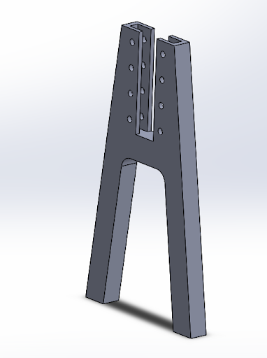
Figure 1. Model of base part.
Figure 2 shows a side-by-side comparison of slot parts. The slot part on the left was the second iteration
design. This piece would provide more support and require less assembly than the very preliminary design, however after the first print trial, it was determined that this design could still be improved upon. The part on the right is the final design. This design includes a curved surface which would better hold the bicycle than the flat surface could.
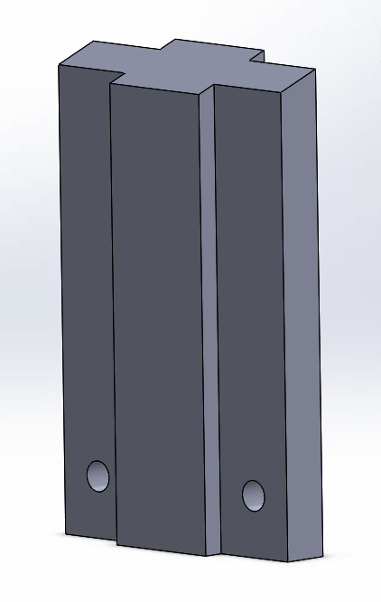
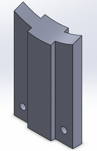
Figure 2. Comparison of adjuster plates from old (L) to new (R) design.
Figure 3 illustrates an assembly of the final design. With a single base part and slot insert this print is
functional as a kickstand device.
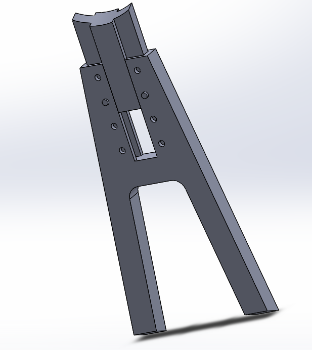
Figure 3. Assembly of base part, adjuster plate and slots
Material Selection
For our first print, the material choice was nylon. This was due to its strength and resistance to corrosion. Nylon has a tensile yield stress of 27.8 MPa and an impact strength of 34.4 kJ/m2[1]. Our second print utilized PLA. PLA has a tensile yield stress of 49.5 MPa and an impact strength of 5.1 kJ/m2 [2]. Ultimaker PLA filament is also made up of organic and renewable resources and is known for having a good surface finish, such that any oils or chemicals from the bicycle gears will not damage the part. However, the main motivation for switching to PLA was the price difference of 4 cents per gram.
Prints
Initial Print
The first prototype of our device was printed using an Ultimaker 3D printer. As previously stated, the initial print was done with nylon filament. In order to stay within print time allowance, a half-scale prototype was produced, with a print time of 5.5 hours, as opposed to 24 hours for a full-scale piece. To reduce the amount of support structures needed, both pieces were oriented flat on the print bed. Additionally, a 20% interior mesh was used with 0.2-inch thickness layers. The cumulation of these three choices were made to best optimize the print time. After the print was completed, it was discovered that the slot part was not small enough to fit within the base part, this error was due in part to improper tolerancing as well as a less precise print from the filament thickness. Images of the initial print may be seen in the project update post.
Final Print
Using the updated final designs, the final pieces were printed using the Ultimaker S5. Since the final prints were so large, this was the only FFF printer capable of completing the print jobs. Overall, approximately 330 grams of material was needed to complete the print for the two base parts, two adjuster plates, and four pegs. Figures 5 and 6 illustrate the final print pieces. The height of the base part in this figure is exactly 11 inches. In Figure 5, the length of the adjuster plate is approximately 3.7 inches. This measurement was taken from the base of the adjuster plate to the center of the top of the plate.

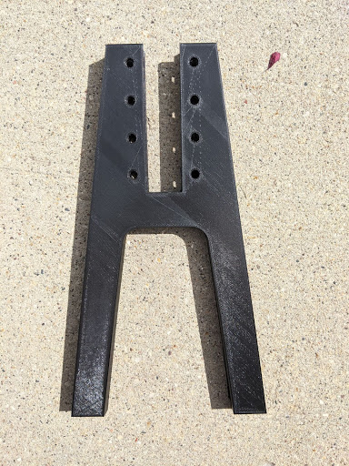
Figure 5. Final print of bicycle stand pieces.
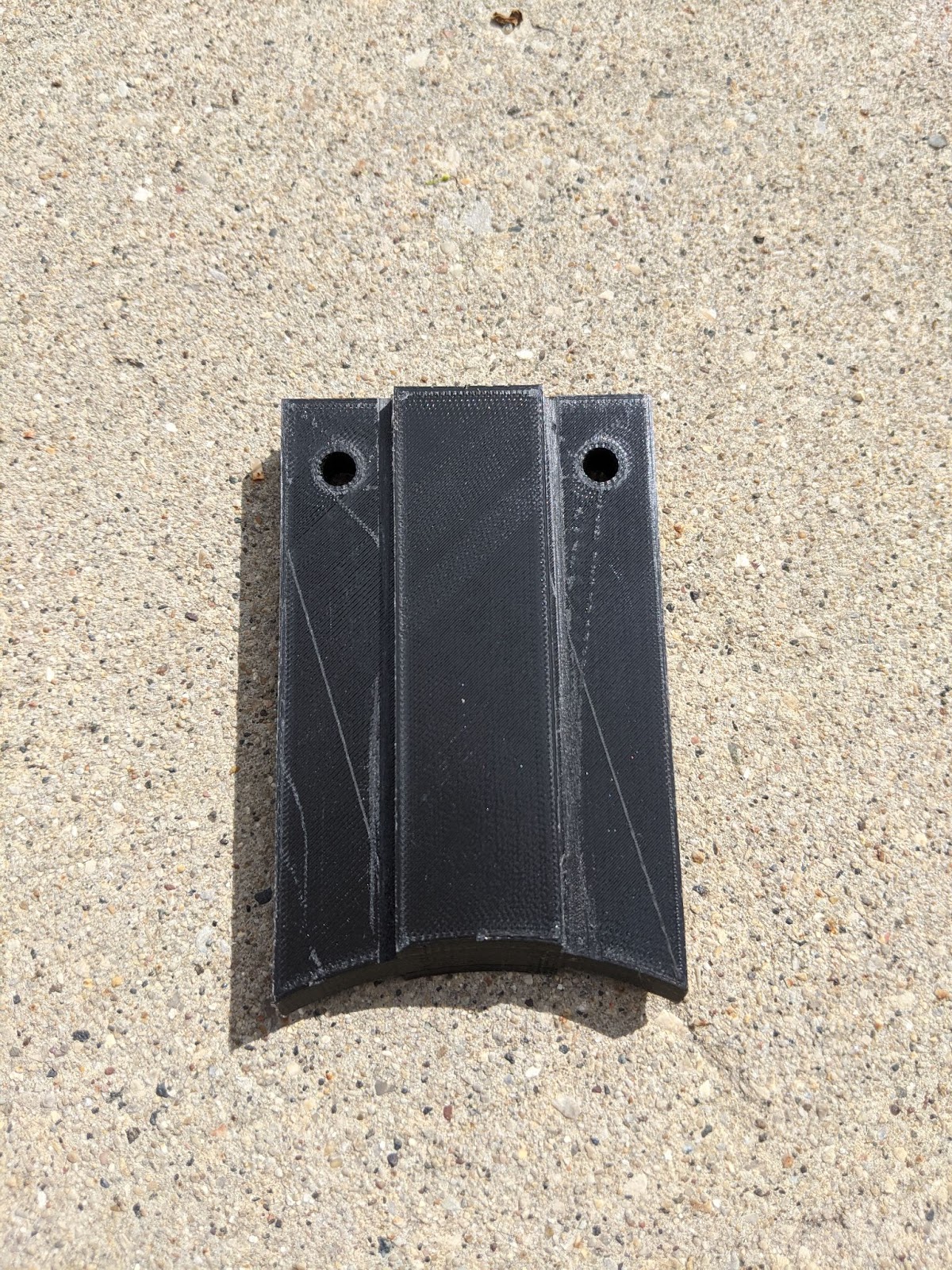
Figure 6. Final print of bicycle adjuster plate.
Figure 7, illustrates the final print assembled in its maximum and minimum height configuration. At its maximum height, the maintenance stand has a height of 14 inches, while at its minimum the adjuster plate is 11 inches.
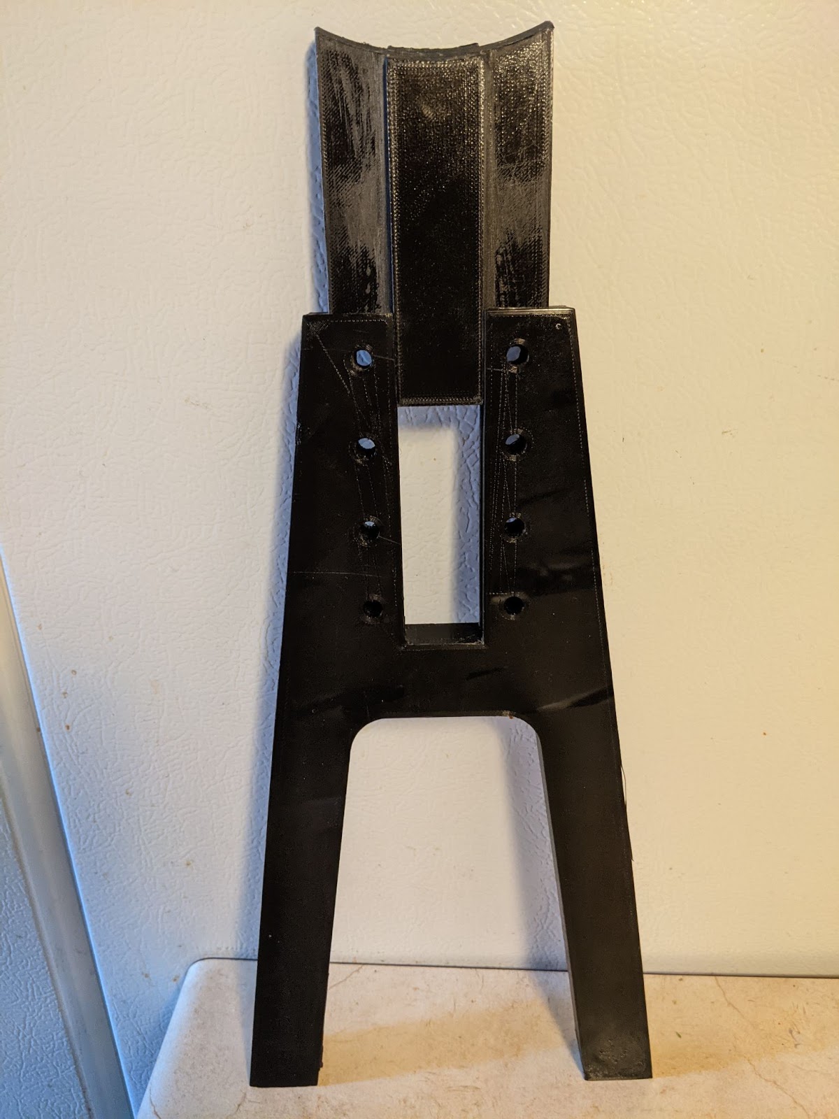
Figure 7. Assembly of slot in highest configuration.
To improve on the tolerancing error present in the initial print, the Solidworks model was improved by making the thickness of the slot part 0.02 [in] less. That way the dimensions of the slots for the peg wouldn’t need to be changed. After the print was completed, postprocessing was still needed to sand down rough edges and allow for a smoother insertion of the slot part. Overall, the increased tolerance helped with the functionality of the final print, however as is common with most manufacturing processes, some post processing was still needed.
Finite Element Analysis
The purpose of the finite element analysis was to ensure that the structural design of the maintenance stand would be able to withstand the forces acting upon both the base and the insert. To model these forces, a brief analysis was performed in Ansys Workbench. Each geometry was loaded into Ansys and given a material selection of PLA, who’s material properties were manually entered. To model the base part, the faces in contact with the ground were assigned a fixed support, then a 28 [N] bearing load was applied to the top four peg slots, since this would be the worst case scenario. This value of 28 [N] came from converting the maximum load of 25 [lbs] into newtons, and then dividing that value equally among the slots. Results of this analysis can be seen in Figures 8 and 9. As shown, the maximum deformation is very small, on the scale of 0.05 [mm]. Additionally, the von-Mises stress results demonstrate that this final design for a bicycle maintenance stand is structurally stable since there are no large stress concentrations, and the maximum stress that develops within the part is well below the failure and yield stress of PLA.
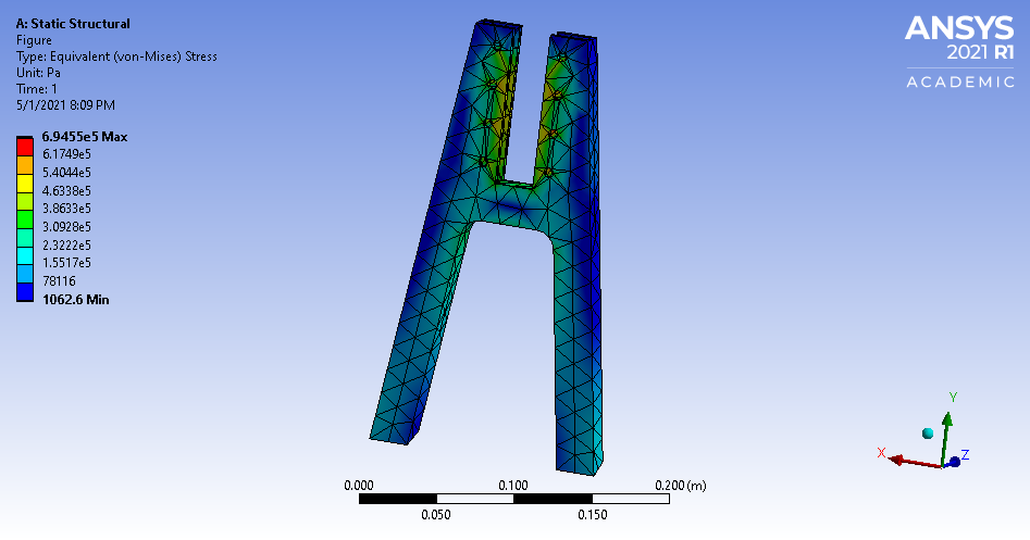
Figure 8. Ansys results of von-Mises stress
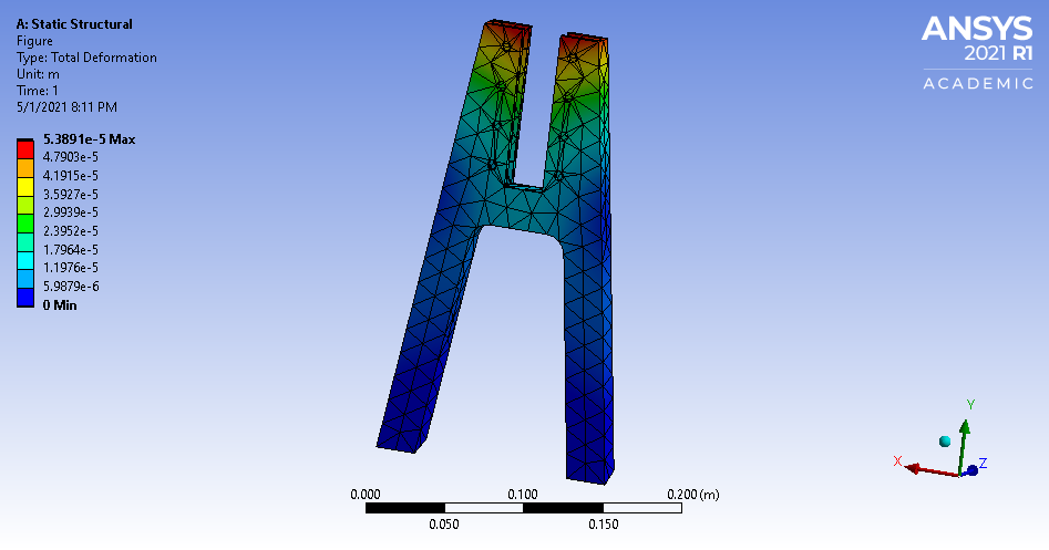
Figure 9. Ansys results of deformation
A similar analysis was conducted with the adjuster plate. With this part specifically, the slots were modeled as fixed since realistically when in use the peg would prevent any movement. Finally, a pressure force was applied over the top surface area of the plate to represent the weight of the bicycle, again by using the maximum case of 25 [lbs].
Again, the deformation of the part can be seen to be minimal, with a maximum value of less than half a millimeter. The von-Mises stress plot also shows that no extreme stress concentrations are developing within the part, and as before with the base part, a maximum stress well below the failure and yield stress of PLA.
These results show that either nylon or PLA could have been the material of choice for prints, since they would both be strong enough to withstand the forces being applied on the parts. However, as previously mentioned, due to cost PLA was the material chosen for this specific final print.
Prototype Testing/ Results
Since the initial print was at a 50% scale to accommodate the trial print time limit, functionality testing was unable to be conducted with the piece. Additionally, there was no access to a child size’s bike, however testing was completed with the final print. This section will discuss the process for testing the print parts, then the following section will discuss the results of the testing and future improvements.
Initially, the bike stand was tested on concrete with a regular sized adult bike. Shown in Figures 10 and 11 below, two configurations were tested. One as a singular assembly as a kickstand and the other as a double assembly to elevate the back tire.
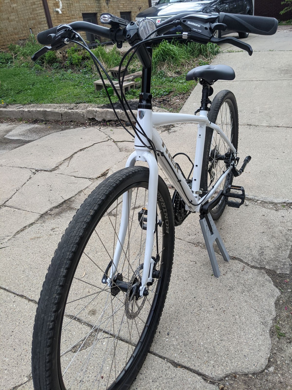
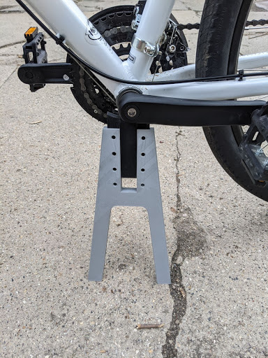
Figure 10. Single stand assembly in kickstand configuration.
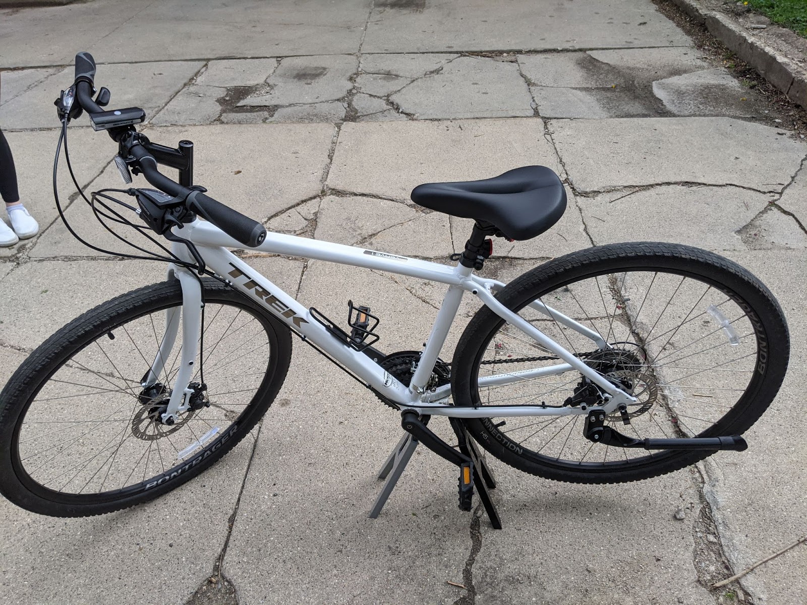

Figure 11. Double stand assembly to elevate the rear tire.
After completing testing on the concrete, testing was moved onto the grass in order to test different terrain. Using the stand on the concrete was simpler due to the level surface, however it was more stable on the grass as the stand was able to dig into the ground for increased stability. This suggests that that stand should be designed to be more stable or maybe add rubber caps to the feet of the stand to increase traction on hard surfaces. The bike was also slightly wobbly on both surfaces. The prototype itself worked well, however could have used some more sanding to assist in the sliding of the adjuster plate as it was slightly difficult to adjust.
Conclusion
The goal of the multi-purpose bicycle maintenance stand was to design and manufacture a portable, easy to use stand for bicycle maintenance. Through initial print trials, a final design consisting of two base plates and two adjuster plates was researched, designed, and manufactured. Due to its availability and cost, PLA was the material of choice for the final print, however Nylon is also a viable material of choice. Additionally, testing was done to assess the functionality of the bicycle maintenance stand. Overall, from testing, it could be seen that the goal of creating a lightweight, easy to use device was met, however, there was definite room for improvement, should there be future iterations of the design.