Max Behrens, Thea Kirkpatrick, David Gruba, Ryan Porter, Evan Mcnamara
Abstract
Hydrofoils for use on personal surfboards are commonly made from aluminum or carbon fiber and are very expensive. We propose that individuals could make their own customized hydrofoils using common 3D printers and materials. Strength, surface finish, and plastic joints are all explored to produce a physical proof of concept.
Introduction
Hydrofoils are a unique way of reducing drag on water vessels. In simple terms, they are wings designed to be used in water. Like airplane wings, they create lift from the difference in fluid velocity above and below the foil and by flow deflection. They have been used on boats, sailboats, paddleboards, and everything in between. Of special interest for this project is use on personal surf boards- as seen in Figure 1.
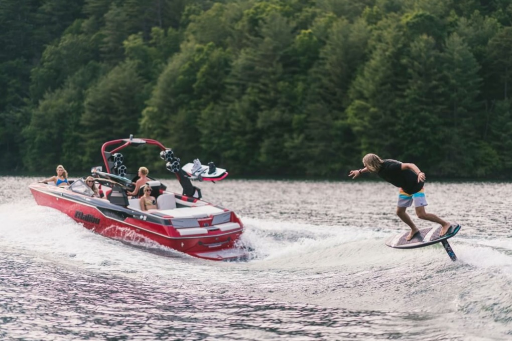 Figure 1. Hydrofoil used to ride a small wave. [1]
Approximately 30 years ago, the first metal hydrofoils were attached to a 3-foot-long mast under the board. This allowed riders to ‘fly’ above the water with very little drag. These metal foils were heavy and expensive. In recent years, companies have begun to sell carbon fiber kits, like the one shown in Figure 2, that are lighter than original models but still expensive (upwards of $1000) [2].
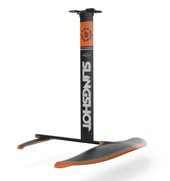 Figure 2. Carbon fiber foil and aluminum mast. [2]
The goal of this project is to produce a hydrofoil and mast assembly using additive manufacturing as the primary manufacturing method. This will serve as proof of concept for a cost-effective, customizable, and lightweight hydrofoil that can be produced with a standard 3D printer and common tools. The cost of materials for our design will be significantly less than that of a carbon fiber or metal hydrofoil. This could open opportunities for individuals with smaller budgets. Furthermore, the low cost and short time-to-build qualities of additive manufacturing could allow people to build many custom foils for varying conditions.
Overall Design
Very early in our design process, we created a full CAD model of a hydrofoil. The model is based off other hydrofoils in the market. This model is shown in Figure 3.
 Figure 3. Dimensioned model of first design. Dimensions in inches.
As seen in Figure 3, we have a multiple component design with several challenges. First, many of the parts are too long to be printed in one piece. This means that they must be printed in several interlocking sections. Second, it is desirable for the parts have thin cross-sections for maximum aerodynamic efficiency. This creates challenges when designing parts that must be stiff and strong. Related to aerodynamics, the surface finish of the parts should be smooth to maintain laminar flow over the foils.
Mechanical Testing
Since hydrofoils are subjected to large hydrodynamic forces as well as the weight of the rider, mechanical strength was of greatest concern in the prototype. The loading conditions of an actual hydrofoil would consist of primarily a downward force on the mast. This would produce a bending or possibly a buckling effect.
Test Part Designs
To test the strength, we had to come up with a simple experiment. Because the time and cost to print a full assembly with multiple variations would be huge, a method to test on a smaller scale was needed. To do this, we decided to take the cross-section of the full-size mast and extrude it 8 inches, with a joint in the middle. This would be a small enough part that several variations could be tested while using a minimum amount of print time. With these experimental parts, we could then run strength tests. Secondly, these experiments allowed us to test joint types, material, print orientation, infill, and surface roughness.
The first joint idea proposed is derived from woodworking, where joints are commonly made between pieces by using interlocking shapes. The chosen woodworking-type joint for this test is a mortise and tenon, shown in Figure 4.
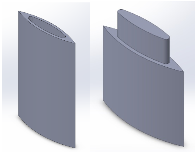 Figure 4. Mortise (left) and Tenon (right) joint test pieces.
These two parts were designed to be a total length of 8 inches when assembled. The parts would ideally slide together easily and JB Weld Epoxy would be applied inside the joint for maximum strength.
The second idea is to use metal ‘ribs’ inside the plastic mast. Two variations of this idea were tested: one large hole in the center of the mast and four small holes organized in a square.
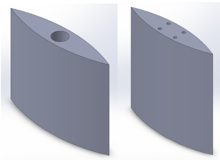 Figure 5. Left: single through hole for a 0.5-inch round metal rod. Right: 4 through holes for 0.125-inch metal rods.
Again, like the mortise and tenon joint test, two of each design were printed so that they could be assembled into 8-inch-long lengths. These metal-rib designs were joined by sliding the round metal stock into each piece with JB Weld and allowed to cure. The expected advantage of the metal rib designs over the mortise and tenon joint is increased stiffness and strength for no added print time and very little extra cost. The strength is essential to the durability of the hydrofoil assembly, and the stiffness is important to its use; when riding a surf hydrofoil, the mast should be rigid to maximize responsiveness and give the rider a high degree of stability and control. The single-though-hole design is expected to be stronger but heavier than the four-through-hole design.
Choice of material for the metal ribs was based on available materials in the TEAM Lab: ASTM A36 Steel, ASTM A108 Steel, 303 Stainless Steel, and 6061-T6511 Aluminum. We chose to use stainless steel for its corrosion resistance and high stiffness per volume. Stainless steel is chosen over aluminum because the size of the cross-section is more important than weight. With that constraint, stainless steel is the best choice.
A material analysis was also done on the plastic. Based on our analysis, ABS was chosen as the best available 3D-printing material based on its strength (yield strength of 55-60 MPa). However, we chose to use PLA for initial testing because of its lower cost and better availability in our manufacturing facility. We decided that PLA would likely have satisfactory properties (yield strength of 45 MPa), and we could switch to ABS for final parts if needed for the strength.
Test Part Manufacturing
As we initially researched printers, we chose the Stratasys printer in the Makerspace because of its large build size and material selection. However, after talking with the Makerspace technicians, we decided to use an Ultimaker FFF printer for our initial experiments. The Ultimaker is preferred because its prints are cheaper and more Ultimaker machines are available than Stratasys machines. The Ultimaker still has the required build size and has acceptable resolution for these prints.
To maximize strength, we printed the parts lying flat, as seen in Figure 6. This meant that the beads would be oriented parallel to the loading direction.
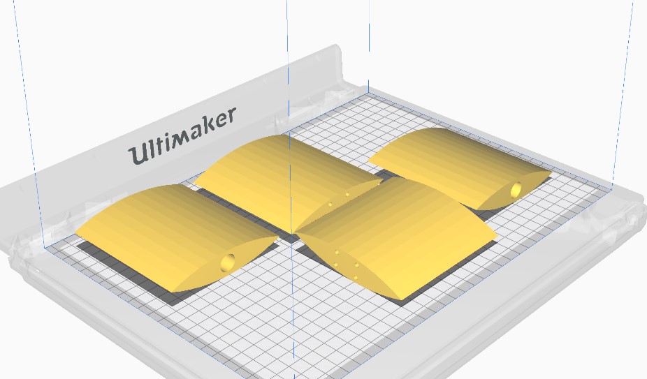 Figure 6. Print orientation shown in the Cura software.
The other print parameters were chosen to minimize print time: default profile of 0.2 and infill of 20%. Pictures of the print for the two steel-ribbed designs are shown below.
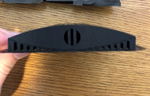 Figure 7. Side view of printed part. Support inside hole can be seen.
As seen in Figure 7, due to the print orientation, there was support material inside the holes. This took extra time to remove and was especially difficult in the very small holes of the 4-ribbed design. After removing the support material, we cut the stainless-steel rods to length and went to insert them into the parts. However, we realized that the holes had not been oversized enough to allow easy insertion of the rods. With some heat and a tap hammer, we were able to insert the rods. For these reasons, the metal-rib design took much longer to assemble than the mortise and tenon joint, which required pliers to remove the supports and filing to clear out the remaining material. However, the assembly time could be greatly reduced with holes that have a larger clearance around the rods.
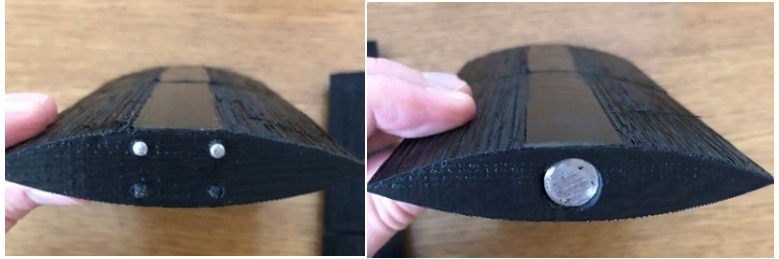 Figure 8. Side view of assembled metal-rod test pieces.
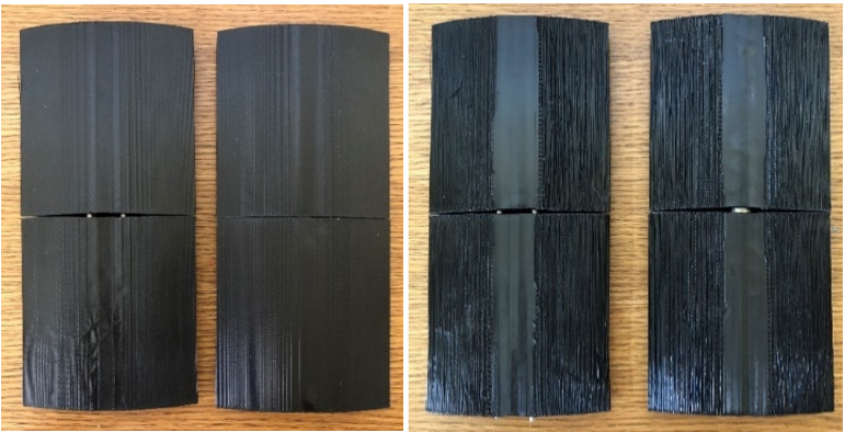 Figure 9. Left: top view of assembled metal-rod designs. Right: bottom view of assembled metal-rod designs.
One disadvantage of the print orientation used is the poor surface finish. As seen in Figure 9, the surface finish on the bottom of the parts was very poor because the material was trying to print on top of the support material. The top sides also had a ‘stepped’ finish which is not as bad as the bottom side, but still undesirable. We were able to improve the surface finish with a combination of sanding, body filler, and spray paint. Figure 10 shows the improved surface finish on one of the test pieces.
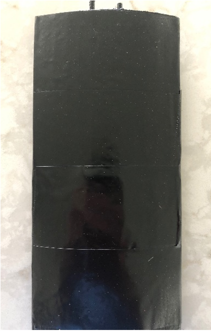 Figure 10. Improved surface finish on test piece.
Calculations
To test the strength of the mast, a 3-point bending test was used on the 3 different prototypes. The data taken is shown in Figure 11. Note that we performed two tests on the 0.5” rod design to see whether the second test would give a similar force vs deflection shape.
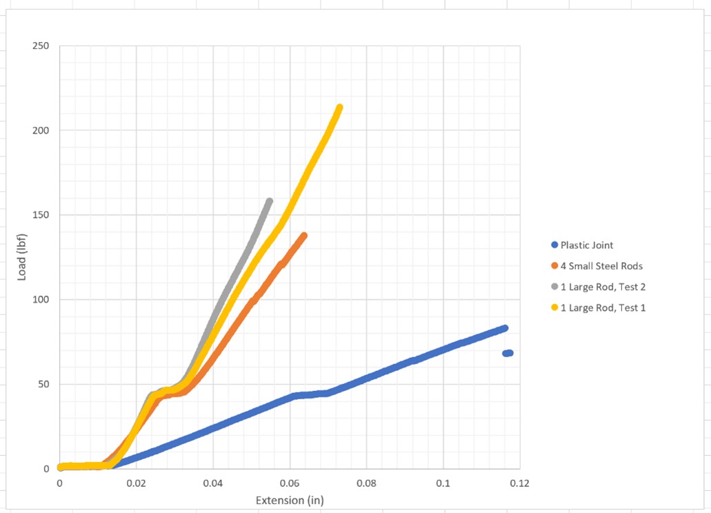 Figure 11. Force vs load raw data for each part.
The data in Figure 11 shows that the 0.5” rod design is the stiffest, the 4-rod design is slightly less stiff, and the plastic joint is the least stiff. All three designs withstood 80 pounds or more without showing any indication of failure. The small break in force at roughly 50 pounds in each design is believed to be related to local failure of the wall or infill at the location of supports.
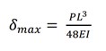
With the force and deflection data in Figure 11, the overall Young’s modulus could be determined using Equation 1, where deltamax is the maximum displacement of the prototype, P is the applied load, L is the length of the specimen, E is the Young’s modulus, and I is the area moment of inertia calculated using SolidWorks.
(1)
With Young’s modulus known, an analytical model for buckling could then be used to predict whether the full-length 30-inch mast would experience buckling. The buckling model chosen was Euler’s critical load, shown in equation 2.
(2)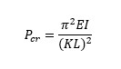
Once the critical load was determined, then practical considerations like the theoretical maximum weight of a rider could be considered. Table 1 shows a summary of the bending tests, with the critical buckling load (Pcr) being the result of each test.
Table 1. Summary of 3-point bending test results.
| Prototype | Maximum Force (lbs) | Maximum Beam Deflection (in) | Young’s Modulus, E (psi) | Pcr (lbs) |
| Plastic Joint | 70 | 0.104 | 11649 | 132 |
| 4×0.125 rods | 140 | 0.052 | 46597 | 530 |
| 1×0.5 rod | 215 | 0.056 | 66449 | 757 |
Results
The values calculated in Table 1 tell us that an all-plastic mast design would not be strong enough. Even if a stronger plastic and larger infill were used, a design with metal rods would be stronger and stiffer. The design with one rod is the best design because it is the strongest and easier to assemble than the 4-rod design. The critical load for buckling with a 0.5” stainless steel rod is 757 pounds. This is with a 30-inch-long mast. Assuming a rider weight of 160 pounds, this design (with the tested printing parameters) is predicted to be strong and stiff enough with a generous safety factor.
It is important to note that this is only a prediction. It is possible that stress or deflection is more critical than buckling. In this case, a model would have to be tested to failure – or in the real world – to ensure a viable design.
Proof of Concept Assembly
With the results of the experiments, we had a way to join sections together and create thin plus stiff parts with a good surface finish. The final assembly is broken up into several components: a base plate, mast, fuselage, front wing, and rear wing.
Airfoil Research
The first step in our final design was analyzing the aerodynamics. With the help of CAD and additive manufacturing, we can make the airfoil any shape that we want and customize it for any conditions. For our project, we will assume a rider weight of 160 lbs and a speed of 10 mph in water. With this information, we searched for an airfoil shape that would maximize stability and minimize drag.
Using dimensionless number equations and recommended sizes of foils in the market (roughly 800-2400 cm2), we predict a front wing surface area of roughly 1200 cm2. Because we do not wish to perform optimization techniques and CFD analysis to select our own foil shape, we will use NACA 1505. This shape is recommended by “PrfctChaos” on an online forum [3].
The NACA designation is a numerical code for the shape. We used an online airfoil plotting code to produce a visual of the shape [4], shown in Figure 12.
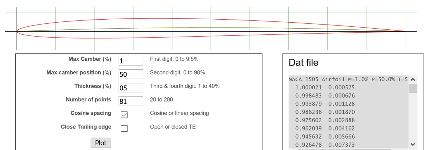 Figure 12. NACA 1505 shape, plotted using an online tool.
Another essential parameter to consider is the angle of incidence of both the front and rear wings. The angle of incidence measures the vertical rotational alignment of the wings with respect to the fuselage. The wings of personal hydrofoils typically have an angle of incidence of roughly 1-3° for both the front and rear wings, but in opposite directions, with the front wing angled upwards slightly and the rear wing angled downwards. Generally, the greater the difference between these two angles, the greater the lift that is produced. Therefore, we decided on an angle of incidence of 3° for each wing (in opposite directions), in order to maximize lift. This does sacrifice some maneuverability at high speed.
There is also significant variation in fuselage length across the market, with standard sizing being roughly every 10 cm starting at 50 cm up to about 80 cm. We selected 60 cm as an intermediate length for our assembly.
Components
For the second iteration of the design, careful consideration was given to both the assembly and size constraints of printers at the UW makerspace. The final mast design is the same as the test mast with a 0.5-inch through hole. However, the final mast would be printed in 3, 10-inch, sections.
The base plate was redesigned for the final assembly. Improvements include streamlining for aerodynamics, stronger bolting locations, and added support for attaching the mast. A drawing is shown in Figure 13.
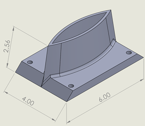 Figure 13. Drawing of base plate, dimensions in inches.
The base plate is designed so that it can be bolted to the bottom of a surfboard. Because the plastic could be squished by bolts, the surface between the board and base plate would also be epoxied together. The mast would mount inside the opening with epoxy for a permanent fit.
With the fuselage design, it was of interest to create a more streamlined form while somehow reducing the difficulty associated with connecting it to the front and rear wings. To accomplish these goals, it was decided to split the fuselage into 3 sections. The main section is the connection to the mast, which features a 0.5 inch through hole where the steel rod extending from the mast can be mounted. The center section is shown in Figure 14.
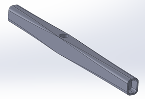
Figure 14. Center section of the fuselage.
As seen in Figure 14, the 3 sections of the mast connect with Mortise and Tenon joints, fixed with epoxy.
The front and rear sections of the fuselage were printed with an extended appendage that allowed for connection to the wings via 0.125-inch metal rods. The major advantage associated with this design is that there is no need to join the fuselage to the wing at their interfaces. The wings are printed with part of the fuselage already connected. An assembly of the 3 fuselage sections is shown in Figure 15. The main wing section is also attached. Both the front and rear wings use the NACA 1505 shape.
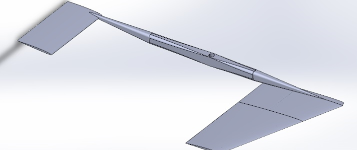 Figure 15. Fuselage and wing assembly.
As seen in Figure 15, only one half of the wings are modeled. This is for assembly purposes, as will be discussed in the next section. The assembly is 32 inches long and would be 24 inches wide with both sides of the wings.
Assembly
For the final assembly of our design, we initially planned to print a full functional prototype. However, the time and cost required to print all of the pieces would have been too large, so we decided to strategically print parts that would save on cost, but still show the viability of our design.
Because we already had an 8-inch section of mast from our testing, we decided not to print the remainder of the mast. However, we did print the base plate and attach the mast to it. This is shown in Figure 16.
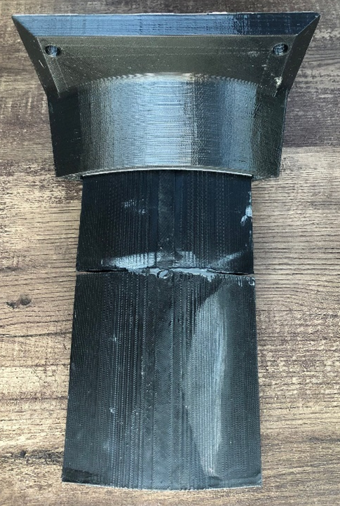 Figure 16. Base plate and mast assembly.
The second half of our final assembly is the actual hydrofoil. Again, to save on printing, we decided to print the full fuselage and only one side of the wings, shown in Figure 17. To show where the mast attaches, we have inserted a short section of the 0.5-inch stainless steel rod. In a full model, this rod would be a continuous piece through all three sections of the mast. To fit the front wing on the print bed, it was printed in two pieces that were joined with 1/8” round rods running through the length of the wing to strengthen it. This joinery would continue through three components for a full front wing assembly. Because the rear wing is smaller, it was printed in one part. If creating a full rear wing assembly, it would be printed in two components and joined with 1/8” rods as well.
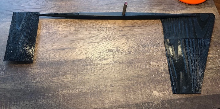 Figure 17. Fuselage and wing assembly.
The physical hydrofoil assembly helps us to understand the viability of the design. As printed, the model does not have a suitable surface finish. But with our technique for smoothing the surface, we could reach an acceptable level of smoothness.
Just by feeling the strength of the assembly by hand, the fuselage appears to be plenty strong. The wings have a small amount of flex. Many aircraft wings are designed to have some flex, so this may be acceptable. The design would have to be tested in use to analyze the wing strength. The wing thickness could easily be increased, or the surface could be wrapped in fiberglass to increase strength.
The full assembly shows that aerodynamic sections of a hydrofoil can be 3D printed and assembled into a smooth and strong shape. Our proof of concept is not ready to use but does show the viability of this manufacturing process and gives insight into further improvements.
Conclusions
The goal of this project was to explore the possibility of manufacturing a hydrofoil for use on a surfboard using additive manufacturing. This would have the advantage over aluminum and carbon fiber hydrofoils in terms of cost and customizability.
Through the course of the project, we learned how to join long, 3D-printed parts using metal ribs. These metal ribs also allowed us to create thin parts with high stiffness. Mortise and Tenon joints were also explored for connecting parts where stiffness is less of a concern. Many print parameters were explored as they relate to strength and surface finish. We showed that the mast (the most strength-critical part) can be made strong enough with 3D-printed parts that utilize metal rods and epoxy for added stiffness.
A final assembly was made as a proof of concept. This assembly shows that a hydrofoil can be 3D printed in an aerodynamic shape and easily be joined together. Although our final assembly is not ready to use, it does provide an outline for a usable hydrofoil that could be made primarily with additive manufacturing.
References
- “Malibu Boats (@malibuboats) • Instagram photos and videos,” Instagram. https://www.instagram.com/p/CLXfuPojLlg/ (accessed Feb. 27, 2021).
- “2021 Slingshot Hover Glide FWING V1 Hydrofoil,” MACkite Boardsports (2021) https://www.mackiteboarding.com/2021-slingshot-hover-glide-fwing-v1-hydrofoil/?gclid=CjwKCAiAm-2BBhANEiwAe7eyFOFV2LXmB-yEqlQYBiam9n0tFwFnumD1ehH7bJezbk2KcNxWslqzUBoCwygQAvD_BwE (accessed Feb. 27, 2021).
- “Wing profile info for backyard hydrofoil builders,” Kiteforum.com (2020). https://kiteforum.com/viewtopic.php?t=2407467 (accessed Apr. 05, 2021).
- “NACA 4 digit airfoil generator (NACA 1505 AIRFOIL),” AirfoilTools.com (2021). http://airfoiltools.com/airfoil/naca4digit?MNaca4DigitForm%5Bcamber%5D=1&MNaca4DigitForm%5Bposition%5D=50&MNaca4DigitForm%5Bthick%5D=05&MNaca4DigitForm%5BnumPoints%5D=81&MNaca4DigitForm%5BcosSpace%5D=0&MNaca4DigitForm%5BcosSpace%5D=1&MNaca4DigitForm%5BcloseTe%5D=0&yt0=Plot (accessed Apr. 05, 2021).