Amy N. Conard, University of Wisconsin-Madison, Madison, WI
Joseph E. Dziekan, University of Wisconsin-Madison, Madison, WI
Abstract
Additive molds are a cheap and effective way to produce rocket fuel grains for low volume production. This study compares the surface roughness of casted fuel grains from one stereolithography (SLA) mold and two fused filament fabrication (FFF) molds with varying layer height thicknesses. Results show that the FFF molds produced fuel grains with a lower surface roughness than the fuel grains cast with the SLA mold. This is the result of the castor oil used for lubricating the molds adhering more effectively to molds with a higher surface roughness. Thus, a film of oil is maintained in these rougher molds that aids in the removal of the fuel grains.
Introduction
In a hybrid rocket, the fuel grain serves two main purposes, the first of which is to provide the fuel necessary for combustion. The secondary purpose of the fuel grain is to act as the combustion chamber [1]. The fuel grain is hollow which allows the oxidizer to pass through and react with the hot fuel on the internal surface of the fuel grain causing combustion to occur. In addition, its physical design has a strong influence on the engine’s performance, which makes it a good candidate for 3D printed molds due to the variety of shapes that can be printed.
The mold shape used is a cylindrical rod because this shape provides a progressive thrust curve during combustion [1]. Three molds of this shape were additively manufactured with varying layer height thicknesses to understand the impact of layer height on the surface roughness of the cast fuel grains. The initial hypothesis is for the surface roughness of the fuel grains to decrease with a decrease in the layer height thicknesses of the molds.
Materials
One low density Formlabs Clear resin was used for a fuel grain mold [2]. This resin has a specific gravity of 1.20 g/cm3, an ultimate tensile strength of 38 MPa, and a tensile modulus of 1.6 GPa [2]. The FFF molds used Ultimaker Polylactic acid (PLA) with different layer height thicknesses. This thermoplastic has a specific gravity of 1.24 g/cm3, a glass transition temperature of 60 °C, and a melting temperature of 145-160 °C [3]. In addition, it has an ultimate tensile strength of 45.6 MPa and a tensile modulus of 2.346 GPa [3].
Methodology
Procedure
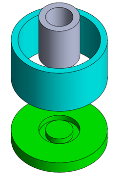
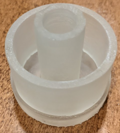
A traditional shape used in fuel molds is a cylindrical core since this provides a progressive thrust force, which means the thrust increases throughout the burn because of increasing burning surface area [1]. This mold was 3-D printed three times on a small-scale for prototyping. Two molds were printed on an Ultimaker FFF printer, one with a layer height of 0.06 mm and one with a layer height of 0.1mm. Another mold was printed with a layer height of 50 microns using a Formlabs SLA printer. After these molds were manufactured, they were used to mold cylindrical fuel grains with an outer diameter of 3.81 cm (1.5 in), an inner diameter of 1.27 mm (0.5 in), and a height of 2.54 cm (1 in). The CAD assembly of the mold and the resulting print can be seen in Figures 1 and 2, respectively.
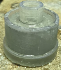
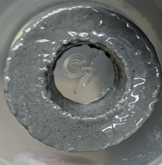
This mold was used to cast an initial sample fuel grain with the predetermined hydroxyl-terminated polybutadiene (HTPB) fuel grain recipe [4], which can be seen in Figures 3 and 4. The inside of the mold was coated with castor oil to assist in removal of the cured fuel grain and this casting process proved to be effective as seen in Figure 4.
Measurements
After the fuel rods have been cast and cured, they must be removed from their mold; however, the fuel rods are not completely rigid after curing. Thus, for proper mold removal, fuel rods must have a smooth surface finish to reduce the amount of surface area in contact with the mold. Less surface area in contact with the mold results in easier mold removal and less deformed fuel rods. The shape of the fuel rod is crucial to optimizing thrust and thus a lower surface roughness results in better burn patterns and more ideal thrust curves.
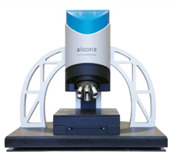
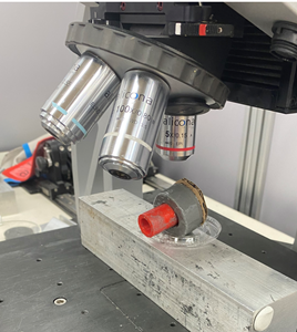
An Alicona Infinite Focus machine, which is seen in Figure 5, was used to measure the surface roughness of each fuel rod produced by their respective cylindrical SLA and FFF molds.
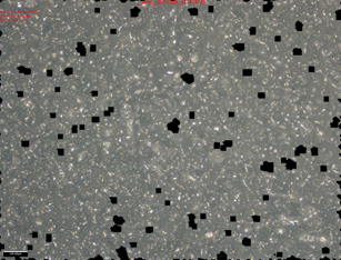
The image shown by Figure 7 was captured by the Alicona Infinite Focus machine and is a 2D photograph of the part’s surface. The black spots are areas that were not in focus when the image was captured due to poor lighting or the fuel rod creeping. To accurately determine surface roughness, those areas must be excluded and an area where no black voids exist must be selected to determine the surface roughness.
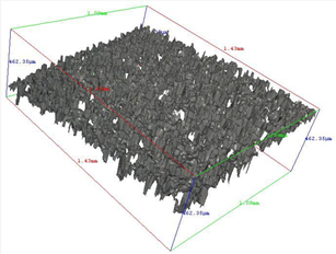
Once an area without any voids is selected, a 3D image of the surface roughness is created, which can be seen in Figure 8, and the arithmetical mean roughness is calculated using the Alicona Infinite Focus machine’s software.
The surface roughness of three fuel grains were measured, one for each mold, and the results can be seen in Table 1.
Table 1. Results of fuel rod surface roughness measurements from FFF and SLA molds
| Part | Color | Layer Height | Print Time [hrs.] | Fuel Rod Surface Roughness [microns] |
| SLA (fine) | Clear | 50 microns | 3.25 | 20.96 |
| FFF (fine) | Black | 0.1 mm | 2.5 | 20.14 |
|
FFF (very fine) |
Black | 0.06 mm | 4.25 | 17.4 |
Results and Discussion
Oil Film Theory
The initial hypothesis was for the surface roughness of the fuel grain to decrease with the layer height of the molds. However, as seen in Table 1, the opposite of this hypothesis was proven to be true. One explanation for this is based on the use of castor oil for lubricating the inner walls of the cylindrical molds.
With a smaller layer height, the surface roughness of the additively manufactured part improves which results in a smoother inner cylinder wall. The castor oil used to lubricate this wall adheres to it less effectively when smooth because gravity draws the oil down the wall and into the bottom of the mold. However, as the surface roughness increases, more oil adheres and thus there is a more effective film of oil between the outer wall of the fuel grain and the inner cylinder wall of the mold. This film allows for a smoother extraction.
As seen in Table 1, the surface roughness of the SLA, FFF (fine), and FFF (very fine) molds were 20.96 microns, 20.14 microns, and 17.4 microns, respectively. In a similar order these molds contain layer heights of 50 microns, 0.1 mm, and 0.06 mm, respectively. This data supports the oil film theory since an increase in the layer height of the molds is associated with a decrease in the surface roughness of the fuel grains.
In addition, trials were conducted without oil, but the fuel grain chemical compound bonded to the inner walls of the mold, thus ruining the molds during extraction. Therefore, all test results included the use of castor oil for mold extraction.
Conclusion
This experiment consisted of varying layer height of the fuel grain molds and seeing the impact on the surface roughness of the fuel grains. One mold utilized stereolithography manufacturing and two molds utilized fused filament fabrication. The surface roughness of the fuel grains was measured on the Alicona machine and surface roughness was shown to decrease with an increase in the layer height of the molds. Surface roughness of the fuel grain mold is crucial to maintaining the shape of the fuel grain, thus the largest layer height mold should be used, which is the 0.1 mm FFF (fine) mold.
References
[1] G. P. Sutton and O. Biblarz, Rocket propulsion elements, 7th ed. New York: John Wiley & Sons, 2001.
[2] “Formlabs Clear Resin Standard Material Data Sheet.” Accessed: May 04, 2021. [Online]. Available: https://formlabs-media.formlabs.com/datasheets/Standard-DataSheet.pdf.
[3] “Technical Data Sheet PLA.” Ultimaker, Accessed: May 04, 2021. [Online]. Available: https://support.ultimaker.com/hc/en-us/articles/360011962720-Ultimaker-PLA-TDS.
[4] Z. Arena, A. Athougies, and R. Alden, “Hybrid Rocket Motor,” Bachelor of Science, California Polytechnic State University, 2010.
[5] “Rapid Roughness and Dimensional Measurements with the InfiniteFocus.” Accessed: May 04, 2021. [Online]. Available: https://www.azom.com/equipment-details.aspx?EquipID=3952.