Project Overview
Optimization of a part can change many details of the design. We will be looking at the design of a bike saddle. We have inherited this project from a graduate student who is working with a bicycle company and the kinesiology department to optimize the bike saddle design. The goal is to make the saddle as light as possible while being comfortable to the rider. The printed saddle will be combined with reinforcement material so it will remain rigid under the force of the rider’s weight.
Project Constraints
There were numerous variables to consider during our FEA studies of the saddle. Our design had to include the fixtures that allowed for the saddle to mount to the bike and the material specifications of both the composite carbon fiber and the epoxy resin. EPX 82 resin was used to print the body of the saddle. Material properties of EPX 82 are listed in Table 1. Properties of the carbon fiber are also shown in Table 2. Thus, the geometry for the mounting design could not be altered and the materials had to be customized to match our design specifications.
Another important variable to consider while conducting experiments was where exactly the stress locations would occur. According to a study conducted by the kinesiology department [2], it has been found that people commonly ride a bike in one of two positions. They are the “tops” position and the “drops” position and can be seen in Figure 1 below. Due to this factor, the stress locations had to be implemented in such a way that either of these riding conditions would be satisfied.
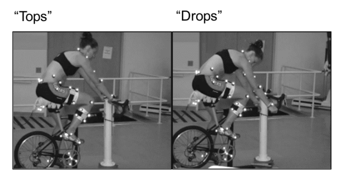
Figure 1. Bike riding positions
A number of constraints were applied to our design from the manufacturing process itself. Since carbon fiber composite is a rigid material, it must have a relatively planar face. The composite also must be cut by hand before being fixed to the epoxy resin so the design had to remain relatively simple so that it could be cut with precision. All of these factors were considered when designing our saddle and running the analysis to ensure ease of manufacturing.
Design Studies
This project was inherited from graduate student Alec Redmann, who had already been conducting similar work for some time. This meant that we had a base design to work off of, as seen in Figure 2. The team decided to continue working on the project by conducting additional design studies investigating where in the saddle high stress regions exist and how they can be mitigated using the carbon fiber insert. To accomplish this, the previously used model was imported to SolidWorks so that design changes could be made, and Finite Element Analysis (FEA) could be conducted. The DLS process used produces parts with minimal anisotropy as seen in Figure 3, so the material can be modeled as isotropic and evaluated with a Von Mises stress condition instead of the Gol’denblat–Kopnov or Tsai-Wu conditions commonly used in analysis of additive manufactured parts. The anisotropy in a traditional 3D printed part can be seen in Figure 4.
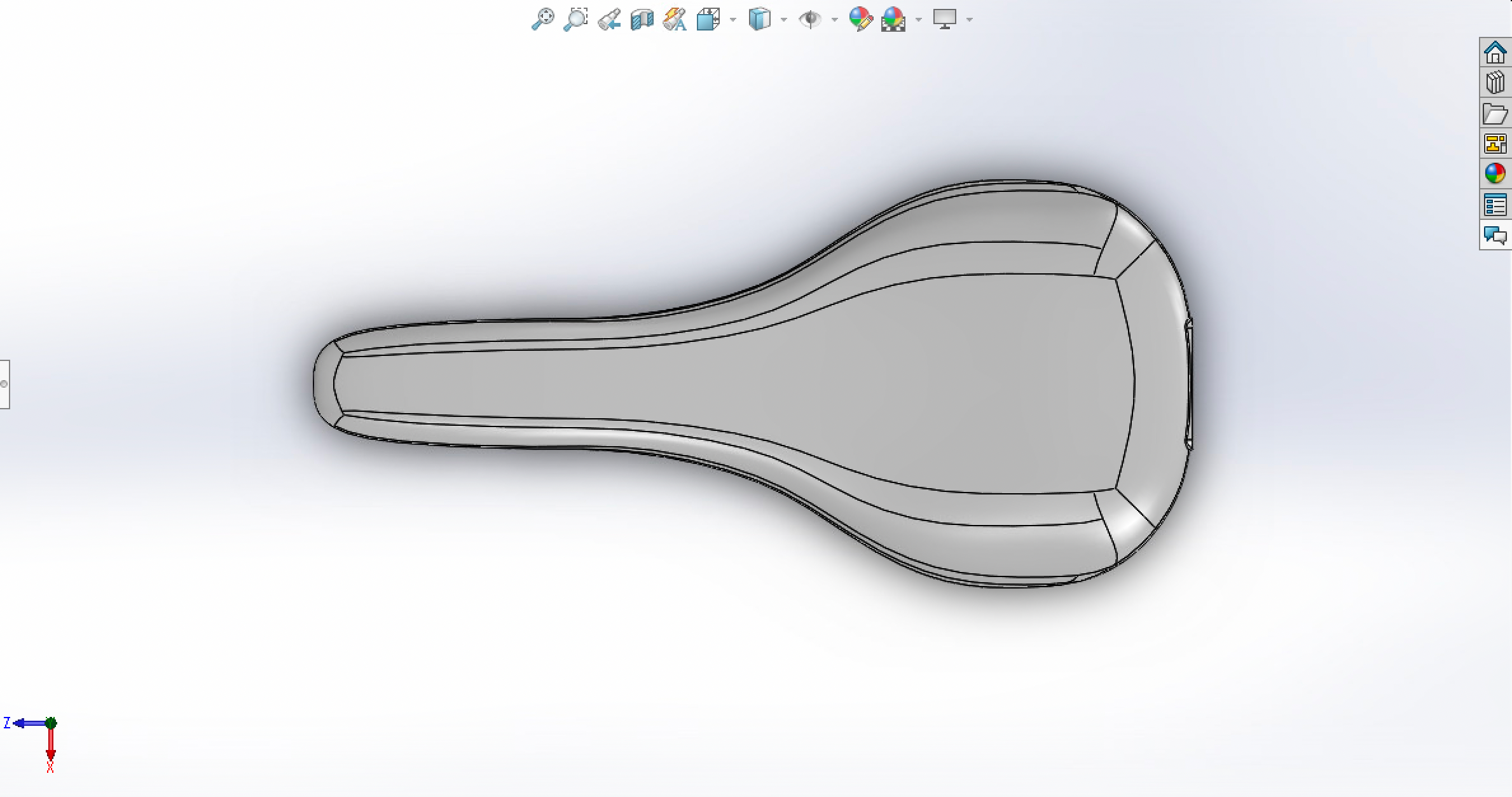
Figure 2. Image of original bike saddle design
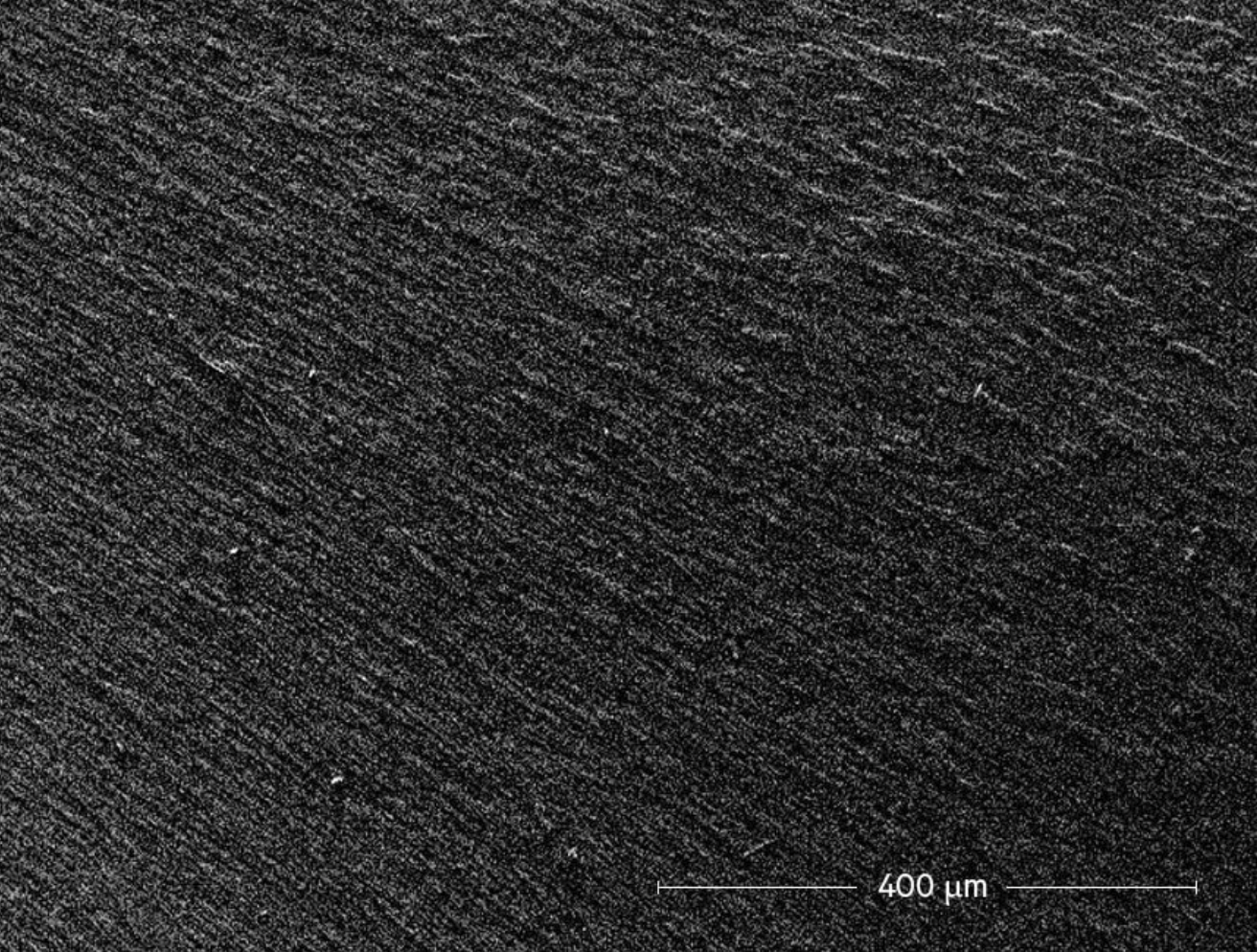
Figure 3. View of DLS printed component with minimal anisotropy from printing process
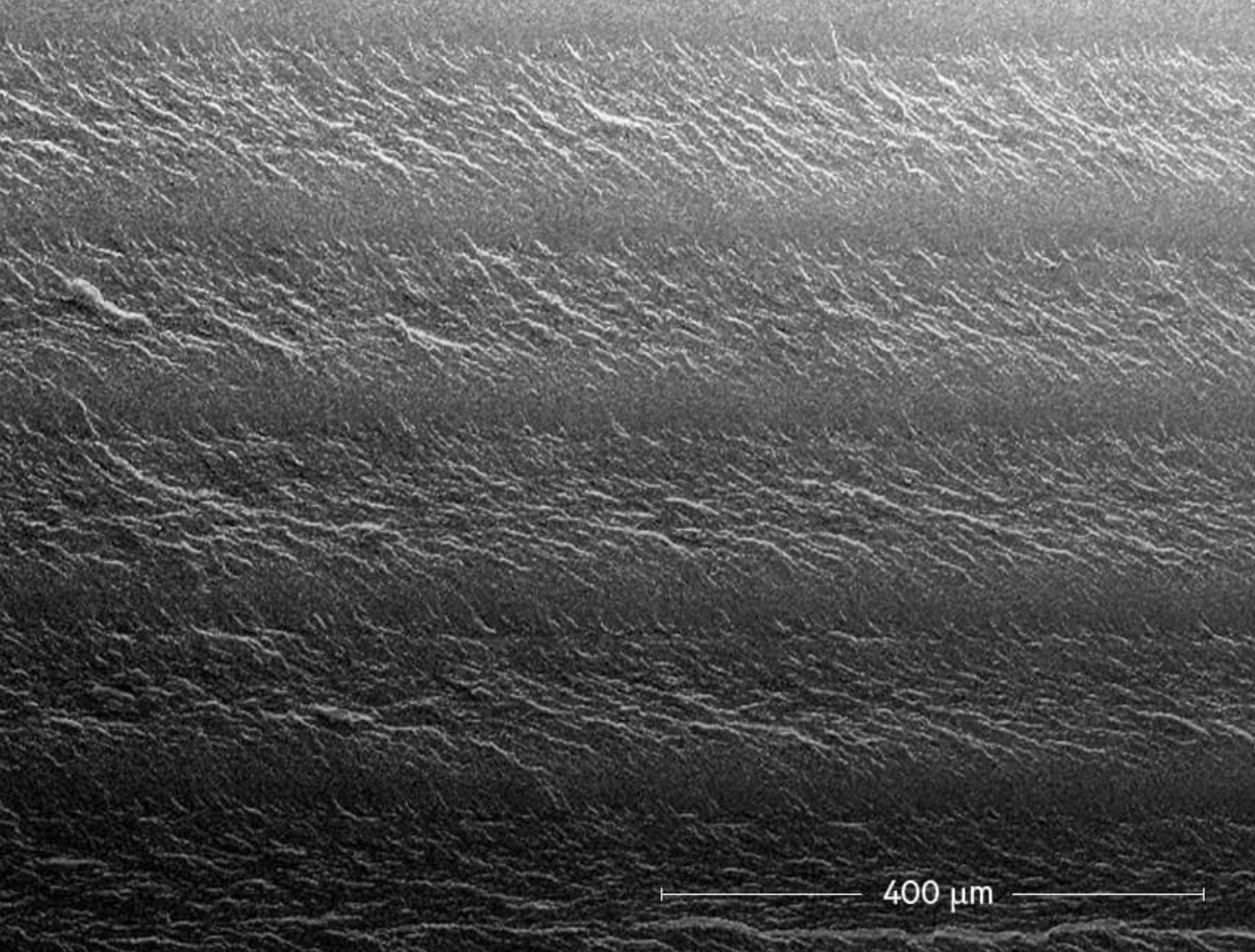
Figure 4. Traditional 3D printed part with significant anisotropy caused by layer-by-layer printing
With an idea of where to start from for optimization, we first took a look at how this original bike saddle design behaved when subjected to different loads. This gave us an idea of how to further enhance the design of the saddle for the stresses it was experiencing. A picture of what this looked like can be seen in Figure 5.
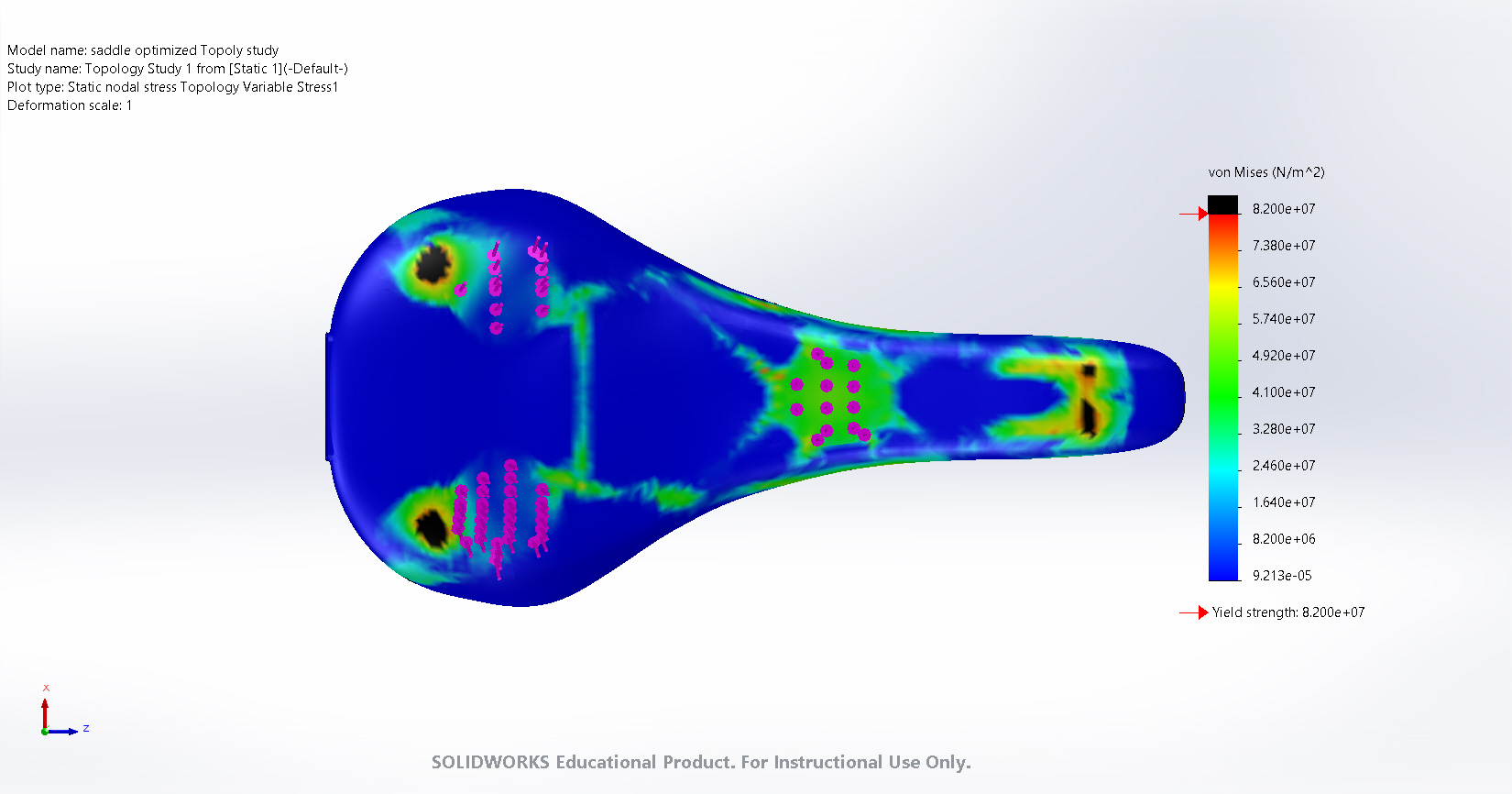
Figure 5. Image of original bike saddle, showing the stress distribution
From here, we next decided to experiment with different ways in which we could remove some of the material of the base of the bike saddle, while still being able to have it function for its intended use. Figure 6 shows a study we did, in which we found the optimal volume reduction while the saddle was under load.
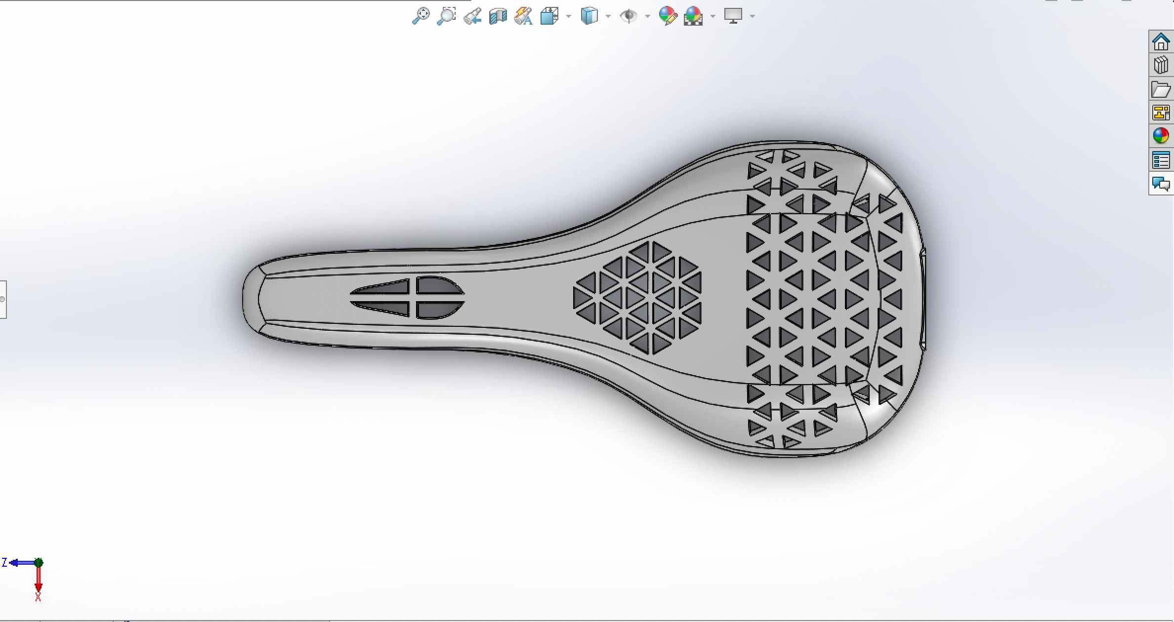
Figure 6. Saddle design with optimized volume reduction
The goal of this was to be as efficient as possible. Removing some amount of material from the base of the saddle would mean we would be saving on production costs. Designing the saddle to have less material results in fewer resources used when actually manufacturing the part, thus saving time and money.
With this volumetric reduced model now being used, we also had to subject it to similar loads as the previous bike saddle to yet again find the points of high stress.
Materials
The hybrid bike saddle structure that was created consisted of two materials: a carbon fiber composite and an epoxy resin. The epoxy resin would make up most of the saddle’s structure, while the carbon fiber prepreg would be added after the main structure was printed for structural support. The epoxy chosen for the printing of the base of the saddle was EPX 82. It’s material properties are listed in Table 1 below [3]. The epoxy is assumed to be isotropic, so material properties do not vary with direction. This assumption is made based on the very thin layer height of the DLS printing process resulting in better bonding between layers and minimal anisotropy.
Table 1: Material Properties of EPX 82 [3]
| Material Properties | Value | Units |
| Ultimate Tensile Strength | 82 | MPa |
| Tensile Modulus | 2800 | MPa |
| Elongation at Break | 5.9 | % |
| Poisson’s Ratio | .33 | – |
The carbon fiber that was used is a woven epoxy resin prepreg called HexPly W3T282-F263 from Hexcel. Its material properties can be seen in Table 2 below [4]. The carbon fiber prepreg is treated as anisotropic, but with uniform properties in the direction of the sheet, as the fibers are woven facing both directions in the plane of the sheet.
Table 2: Material Properties of HexPly W3T282-F263 [4]
| Material Properties | Value | Units |
| Nominal Ply Thickness | 0.18 | mm |
| Tensile Strength in Fiber Direction | 570 | MPa |
| Tensile Modulus in Fiber Direction | 60.7 | GPa |
| Glass Transition Temperature | 188 | °C |
Composite Design
Through CAD simulation, we determined the areas that we could remove material from and areas that needed reinforcement. First, we conducted a stress analysis and topology study to identify the areas that needed the most reinforcement as was shown previously in Figure 5. Then, the design was revised to create the recess shown in Figure 7.
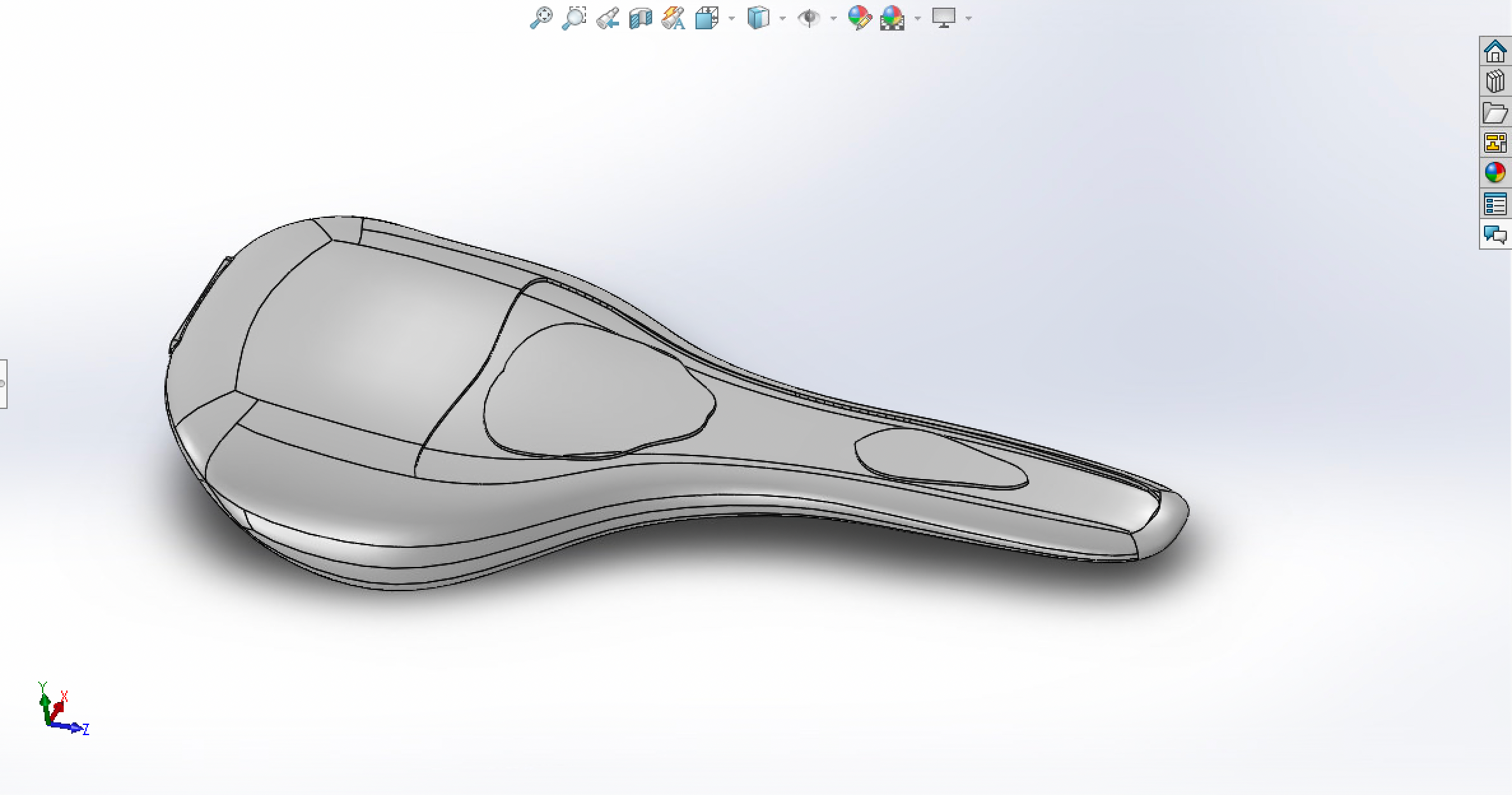
Figure 7. Image of bike saddle with recessed area for composite addition
Volume Reduction Design
After identifying the areas to add carbon fiber composite to, we combined them with the locations that excess material could be removed from to further reduce the mass. This total mass reduction was then analyzed to find the effect on the overall part stress with the carbon fiber which is shown in Figure 8.
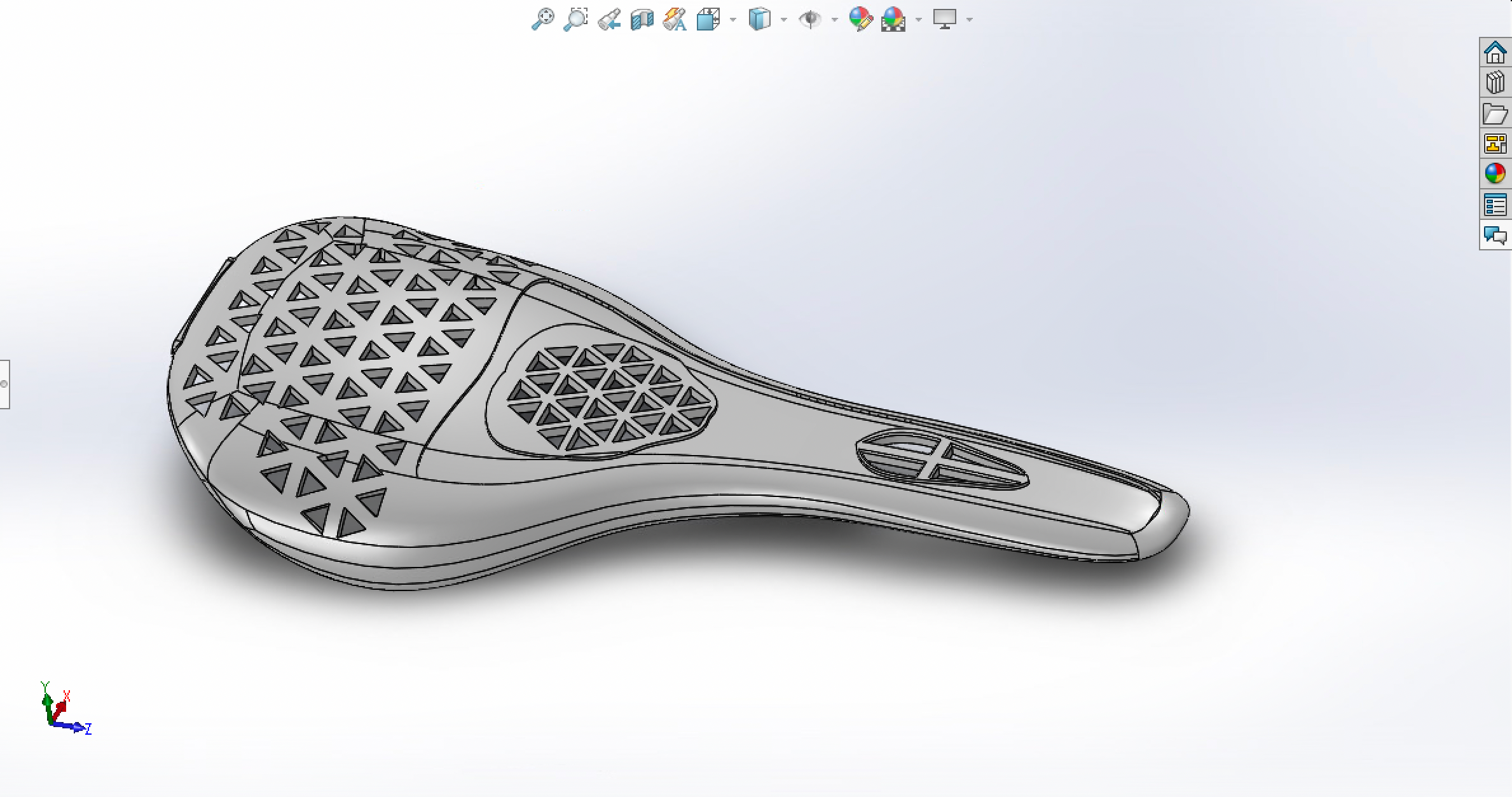
Figure 8. Image of bike saddle with recessed area for composite addition and volume reduction
Final Design
Once we ran our FEA analysis, created the cutout for carbon fiber reinforcement and reduced the volume of our model, we were finally able to print a couple of iterations of our part. Our team was fortunate that Alec Redmann had left over EPX 82 which he used to print our part. The exact cost of the part is not known due to the resin being donated. Alec Redmann has stated that a tube of resin is around $200. Each printed part used 130 g of resin. It is estimated that one printed bike saddle using this process is around $100.
First Print
The first print was successful. The part still on the print platform after it was complete can be seen in Figure 9. The saddle off of the build plate can be seen in Figure 10. The part took around 12 hours to print. The part was initially thermally cured without the carbon fiber insert due to some defects which were noticed. First, the front of the carbon fiber cutout was not straight. Also, it was determined that the cross-shaped cross section in the front was too thin. Since this part had defects, we knew we were going to print a second part and used this print as a proof of concept and to check the design for defects.
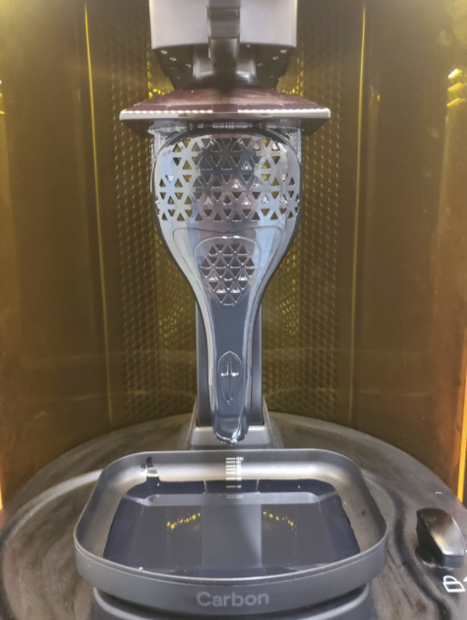
Figure 9. Our first printed part still on the print platform
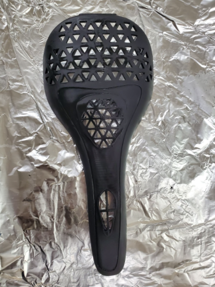
Figure 10. The bike saddle once it was taken off the print platform
Second Print
Once we received the feedback from Alec on how to improve the design, we changed them in the SolidWorks model. First, we made the carbon fiber cutout area in the front of the saddle so that it was straight and symmetric. Next, the cross-shaped cross section in the front was increased in size to make it stronger and fillets were added to reduced stress concentrations at the sharp edges. Once the CAD file was completed, Alec set up the second print for the team. The completed part can be seen in Figure 11. This part had the carbon fiber inserted into the cutout which was designed for the insert and thermally cured to create a strong bond between the EPX and the carbon fiber. The composite part can be seen in Figure 12. To ensure the part met the specifications, the cured part had the mounting brackets inserted confirming they fit. The complete bike saddle setup can be seen in Figure 13.
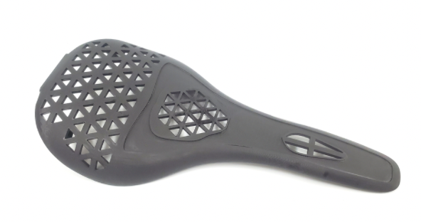
Figure 11. The completed part from the second print
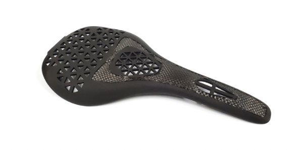
Figure 12. The 3D printed bike saddle co-cured with the carbon fiber insert
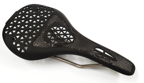
Figure 13. The completed bike saddle with the mounting brackets
Conclusion
Data was collected in partnership with the kinesiology department. Using the dimensions for the saddle mounting brackets, a preliminary CAD file was created. We had inherited these from Alec Redmann who had students work on this project with him previously. Our team ran FEA analysis using SolidWorks to determine the high and low stress areas of the bike saddle. Using this data, we created a surface model and created a cutout for a carbon fiber insert in the high stress locations. Next, we removed material in low stress areas to optimize the design. This reduced the weight as much as possible while ensuring structural integrity. The part was printed using a Carbon M1 DLS printer and the material was EPX 82. Since the first saddle was not ideal, it was thermally cured without the carbon fiber insert. Alec gave suggestions on how to fix the part and the CAD file was changed. A second part was printed and thermally cured with the carbon fiber to create the composite part. Both prints took around twelve hours to print and about a day to fully cure. With the assistance of Alec, the team was able to successfully print a composite bike saddle using a DLS print process and thermally cure it with carbon fiber reinforcement. With the price per bike saddle, this method would not be very practical. However, the goal of optimizing the bike saddle and creating the composite part was achieved.
References
- Riccardeli, C., Carbon Fiber Fabric and its Potential use in Object Conservation, Objects Specialty Group Postprints, Volume Twenty-Four, p. 147-167, 2017.
- Chen, H., Redmann, A., Zhang, R., Mecham, S., Osswald, T., 3D Printed Hybrid Composite Structures – Design and Optimization of a Bike Saddle, 2020.
- Carbon, Inc., EPX 82 Resin: Technical Data Sheet. 2019.
- Hexcel. HexPLy F263 Data Sheet. 2016.