Jack Fahy, University of Wisconsin-Madison
Gunnar Maples, University of Wisconsin-Madison
Evan Ogren, University of Wisconsin-Madison
Abstract
A tap handle is designed, fabricated, tested, and post-processed for Hidden Cave Cidery’s tasting room. Cidery owner Walker Fanning gave vital design feedback to cater the aesthetic to the brand’s values of local honey, local apples, and barrels from a local distillery. Industry testing standards are applied to the design and a benchmark mechanical finite element analysis (FEA) is used to predict failure. A final product is painted and gifted to Hidden Cave Cidery.
Introduction
Tap handles are a vital component in a beverage’s branding. Owner of the local brewery Working Draft Ryan Browne calls them a “mini-billboard” to the consumer [1]. However, there is a hurdle to this point-of-purchase advertisement: cost. Kelsey Cooper, a project manager at Taphandles in Seattle, WA, estimates that the unit price for small (less than 100) batches of handles can reach over $30 per handle [2]. Furthermore, Ms. Cooper suggests low volume requests would need to use pre-made handles to reduce design costs. The ME 514 team found a local cider maker, owner of Hidden Cave Cidery Walker Fanning, who needs a tap handle for his opening tap room in Middleton, WI. Specifically, he needs a tap handle for his barrel aged ciders.
Additive manufacturing’s design freedom allowed the team to design a tap handle specific for Mr. Fanning’s specific beverage’s brand. Additionally, this project gave the team the opportunity to iterate on designing with additive printing constraints and explore the details of printing and post-processing additive parts.
This report reviews the design of the tap handle, the fabrication steps, the experimental and numerical evaluation of the tap handle. This report concludes with the preparation of the tap handle for tap room use.
Tap Handle Design
Meeting with Walker and brainstorming ideas generated the initial design: a stack of three symbols: the apple, the Langstroth beehive, and the whiskey barrel seen in Figure 1. The apple and hive symbols are essential because while a cidery owner, Walker is also an Orchard Manager at Eplegaarden in Fitchburg, WI. He respects local agriculture and therefore uses locally sourced apples and honey. In fact, Eplegaarden is pollinated by the bees that make this honey. The barrel is unique as he is partnered with Old Sugar Distillery in Madison, WI where he gets the barrels for aging. The initial sketch of the design is pictured in Figure 1.
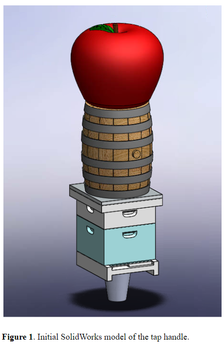
The stack of three symbols are designed to be printed individually to allow for module printing, sanding, and painting. Additionally, individual printing allows for lower cost of print failure as the entire design did not depend on one successful print.
Finally, a tap handle needs a ?-16 female tapped threads of 1inch depth to fasten to a faucet tapped with a beverage. An aluminum rod was turned, drilled, and tapped to act as both the fastener for the handle and as a structural core mating the three individual components. The three prints will be painted, epoxied to the handle, and finished in a clear acrylic spray to prevent any paint wear.
Materials and Printing
The client, Walker Fanning, gave the team feedback on the design after the initial SolidWorks models were developed for the apple, barrel, and Langstroth beehive. Adjustments were primarily made to the beehive’s aesthetic to make it more representative of typical Langstroth beehives. This included making the bottom box slightly larger than the top box and adding a slot that bees use for entering and exiting the hive as seen in Figure 1. The barrel model was simplified by reducing the number of planks. No changes were made to the apple model. Colors were also adjusted according to our client’s feedback.
FFF printing was chosen as the printing method because of its simplicity, fast print time, and more readily painted material choices than SLA. Cura was used to determine printing time and decide on print parameters. The initial approach was to print each part separately at 0.1 mm layer height and 20% infill without support structure in order to preserve visual integrity and obtain a smooth surface finish. However, the barrel and beehive models produced significant print times exceeding 12 hours each. Thus, iterations were conducted by scaling the models and adjusting the infill and layer height parameters. After consulting with the client, the team decided to scale down the total height of our tap handle from 8.4” to 7”. After these changes, the LxWxH of each part was as follows: Apple (2.5”x2.5”x2.25”), Barrel (1.92”x1.92”x2.5”), and Langstroth beehive (2.04”x1.85”x2.25”). Even with these sizing changes, and adjusting the layer height to 0.2 mm, print times still exceeded the 8 hour limit. As the aesthetic and finish of the part surfaces is vital to this project, the team moved forward with this final iteration to avoid further reductions to part quality. Although a 0.2 mm layer height produces a rougher surface finish than 0.1 mm, the team deemed that sanding of the part surfaces would be sufficient to ensure a smooth finish.
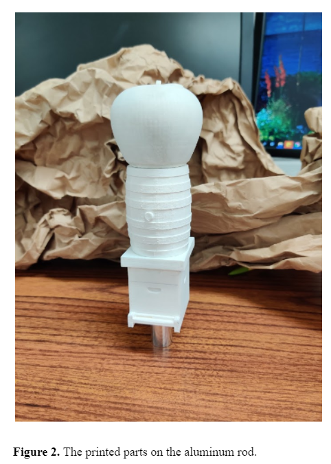
The 3 parts were printed simultaneously on one Ultimaker S3 printer (Figure 4) at the UW-Madison Makerspace with printing parameters of 0.2 mm layer height, 20% infill, and 0.4 mm nozzle. The shell thickness was designated as 0.8 mm thick (2 nozzle diameters). Parts were printed in white Ultimaker PLA with supports and adhesion. PLA was chosen because it has adequate material strength, can produce fine details, and can be readily painted with acrylic paints [3,4]. The total print time was 9 hours and 55 minutes and the amount of material required was 141 grams. The print was successful on the first attempt and part quality was better than expected. The printed parts are imaged in Figure 2.
Experimental Testing
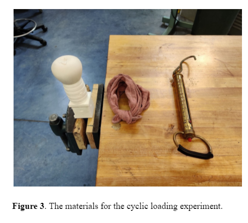
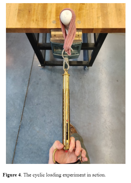
The printed parts and rod were assembled without epoxy to test the structure against an industry’s standard cyclic loading requirement. Dave Kaplan, the vice-president of engineering at Taphandles, tests his tap handles with 20lbs of force loaded 50 times perpendicular to the column’s axis to create cyclic bending stresses. The test on the printed parts was carried out with a spring scale and rag with the materials pictured in Figure 3. The rod’s base was fixed in a soft-jaw vise. The rag was wrapped around the top two prints to simulate a hand grasp with the scale pulling on the rag. By choosing the top two prints, the bending stresses cycled were the highest possible. The scale was pulled 50 times to the 20lbs mark on the scale. The test in action is seen in Figure 4. No deformation in the prints or rod was noticed, therefore the design passed the industry standard.
Numerical Simulation
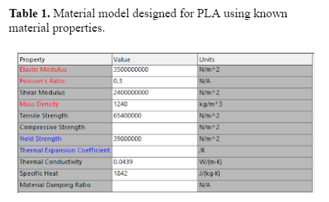
Finite element analysis was conducted in SolidWorks on the tap handle assembly. The goal was to estimate the stresses that the tap handle may experience and ensure it will not break during regular use. First, a material model for PLA was created in SolidWorks using existing values for PLA material properties (Table 1) [5,6]. 3D printed PLA is anisotropic, but for the sake of simplicity the PLA material was assumed to be linear elastic isotropic. The metal rod and ferrule were modeled as 1060 aluminum alloy. Fixed surfaces were prescribed at the ferrule base and at the interfaces between parts. A static load of 20 lb was distributed over a surface on the barrel representative of a hand pulling the handle. This load was selected because it is the standard load used for testing tap handles in industry [3]. To account for the infill structure of the 3D printed parts, this simulation was conducted on the tap handle assembly with both solid body parts and shelled parts (with wall thickness equal to the printed wall thickness of 0.8mm) to obtain a range of results that the actual mechanical response of the handle should lie within.
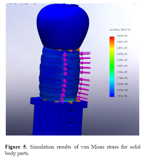
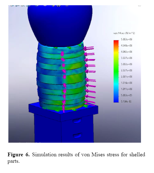
Distributions of von Mises stress, equivalent strain, displacement, and factor of safety were obtained from the simulations. Peak displacements of the barrel were found to be fairly negligible, ranging from 4.487e-4 mm and 8.695e-2 mm for the solid and shelled parts respectively. Equivalent strains were also of negligible magnitude, with peak values ranging from 2.125e-5 and 7.448e-4 for the solid and shelled parts respectively. These peak strains occurred at the junction of the barrel and Langstroth beehive.
Von Mises stress distributions showed peak values of 0.1526 MPa for the solid parts and 4.548 MPa for the shelled parts as seen in Figures 5 and 6. These peak stresses were again found at the junction of the barrel and Langstroth beehive, indicating the mated part surfaces as the most likely location of failure. However, considering the yield stress for PLA was taken as 38.9 MPa, the handle is still significantly far from yielding, and thus appears to be at minimal risk of failure [5]. This is further demonstrated by the factor of safety (FoS) distributions, which show the lowest FoS from either simulation as 7.876 in the shelled parts. It is clear from these simulations that the mechanical response of the handle falls into very safe ranges. We can therefore conclude that the tap handle is at very minimal risk of failure, and thus is ready for industry use.
Final Product
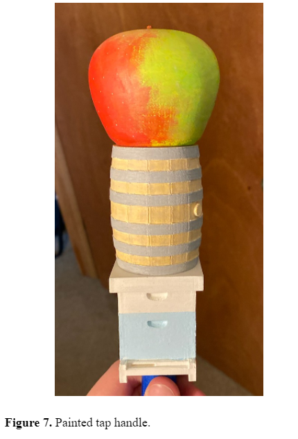
The final tap handle, painted and assembled, can be seen in Figure 7. Once it is epoxied and finished with acrylic, it will be given to Walker Fanning for his time and patience.
Conclusion
The technology of additive manufacturing allows for significant tap handle design freedom and decoupling from traditional batch sizes. Experimental testing was conducted and corroborated with FEA simulations. Both tests proved that the tap handle is strong enough for industry use. The team was successful in developing a product that could be used in industry. Future work is needed in evaluating the economic viability of additive manufacturing in the tap handle industry.
Bibliography
[1] Ryan Browne, “Working Draft’s Tap Handles,” Feb. 10, 2021.
[2] Kelsey Cooper, “Taphandles Project Management,” Feb. 11, 2021.
[3] “Ultimaker PLA material: Highly versatile, easy to print,” ultimaker.com. https://ultimaker.com/materials/pla (accessed May 03, 2021).
[4] J. A. Travieso-Rodriguez, R. Jerez-Mesa, J. Llumà, O. Traver-Ramos, G. Gomez-Gras, and J. Roa Rovira, “Mechanical Properties of 3D-Printing Polylactic Acid Parts subjected to Bending Stress and Fatigue Testing,” Materials, vol. 12, no. 23, p. 3859, Nov. 2019, doi: 10.3390/ma12233859.
[5] “Overview of materials for Polylactic Acid (PLA) Biopolymer.” http://www.matweb.com/search/DataSheet.aspx?MatGUID=ab96a4c0655c4018a8785ac4031b9278&ckck=1 (accessed May 03, 2021).
[6] S. Farah, D. G. Anderson, and R. Langer, “Physical and mechanical properties of PLA, and their functions in widespread applications — A comprehensive review,” Adv. Drug Deliv. Rev., vol. 107, pp. 367–392, Dec. 2016, doi: 10.1016/j.addr.2016.06.012.