Overview
Foldable knives are a useful tool with a purpose in many settings, including both industrial and environmental applications as well as personal use. These knives are designed with two scales that are either riveted or screwed to one another to make up the handle. The complete handle can be made from a variety of materials to target different conditions and uses for various knives.
In the Project Proposal, a preliminary SolidWorks model was created, and an initial print was planned for both scales. The initial print was done using FFF with Ultimaker nylon. Subsequent prints were planned using SLA with various Formlabs resins to compare printing methods. Finite element analysis was done for each scale design to ensure that the object is drop-resistant, which is the primary expected mode of failure for this object’s application.
Table 1: Print trials and associated details.
| Print Type | Material | Print Time | Date |
| FFF | Ultimaker Nylon | 3:30 | 3/23/2021 |
| SLA | Formlabs Tough | 5:45 | 3/31/2021 |
| SLA | Formlabs Rigid | 5:45 | TBD |
Initial FFF Print
Once the FFF print was created, it was installed onto the knife assembly. The screw holes on the scale did not perfectly align with the metal liner for this print trial. This misalignment could be attributed to the imprecision of FFF printing or expansion of the material during or after printing.
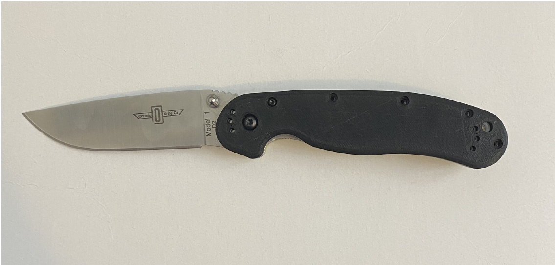
Figure 1: Initial FFF scales fastened to the metal knife assembly.
SLA Print
A second print was carried out using SLA with Formlabs Tough. The SLA scales fit correctly onto the knife handle and all screws could be installed.
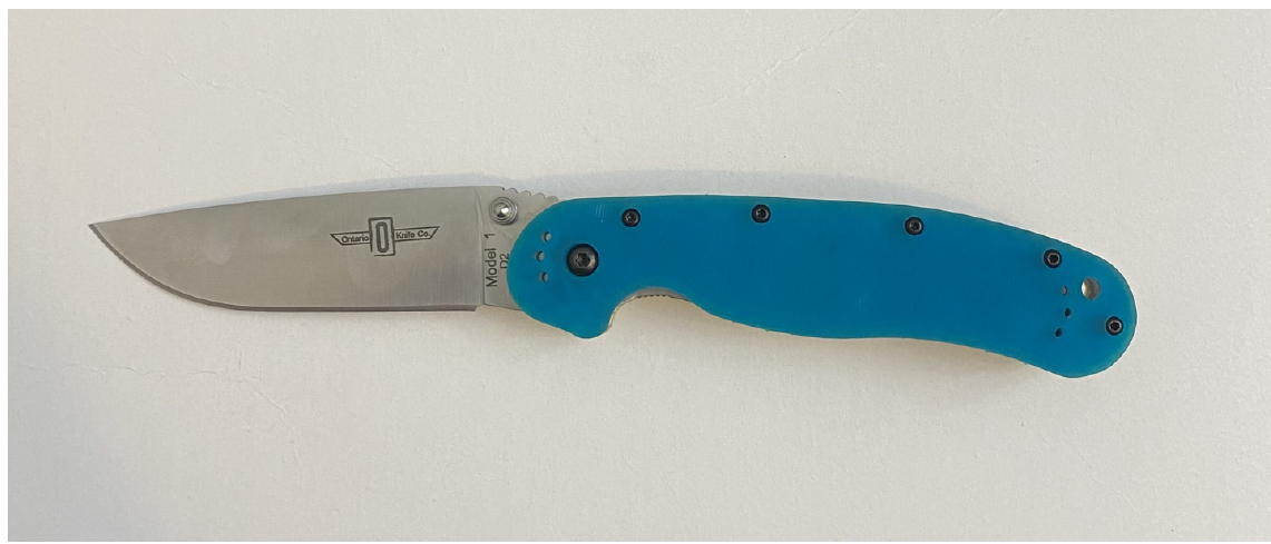
Figure 2: SLA scales fastened to the metal knife assembly.
FFF and SLA Comparison
Figures 3 & 4 show the FFF and SLA scales from the front and back. Overall, the SLA print is more dimensionally accurate and rigid, but has a worse surface finish. This is caused by the support structure used in the SLA process. It consists of many small pillars holding up the handle scale as opposed to FFF which only included a thin layer of material. This is particularly evident in Figure 4, where the pillars, after removal, resulted in small divots in the material. Another interesting feature of the SLA scale is that the entire surface has vertical ridges. These ridges were not included in the STL file, but they make the scales feel better and provide more grip than the smooth FFF ones.
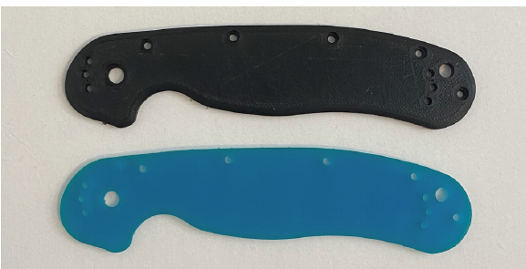
Figure 3: Comparison of FFF and SLA scales
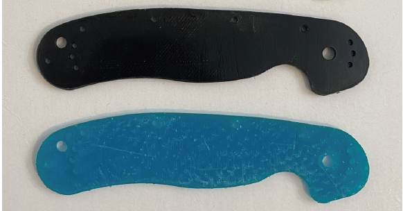
Figure 4: Comparison of backside FFF and SLA scales
Redesign
The results from the initial prints and experiments discussed above lead to a redesign of the part since there is still room for improvement in terms of ergonomics and strength. The surface was changed to include a pattern which resulted in an increased thickness of the scale. The increased thickness is expected to improve the impact strength of the scale.
Another focus of the project is to show the power of additive manufacturing and how it can be used to create unique shapes and designs. The initial prints were very successful in showing that these scales could be produced with relative accuracy and with a quick turn-around time. The redesign that will be used moving forward in SLA printing trials can be seen in Figure 5.
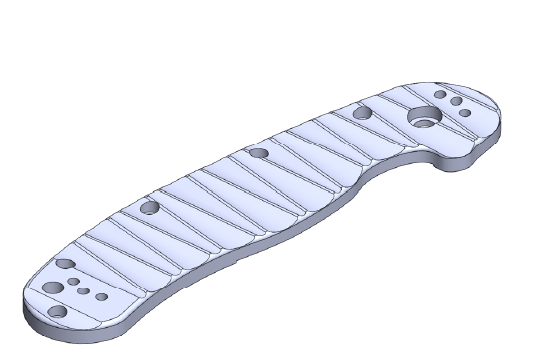
Figure 5: Redesigned scale after initial print trials
Finite Element Analysis
Simulations were run using the SolidWorks Drop Test feature for each scale (front and back) individually, and the results were almost identical. As a result, the front scale (with the lock cutout) was used for full analysis since it experienced slightly higher stresses than the back scale.
Preliminary simulations were also carried out by dropping the scale in x, y, and z directions. The scale experienced the greatest stress when dropped vertically with impact illustrated below with the red arrow, so only results for these conditions are considered.
FEA was carried out for the initial design, as well as the redesigned scale with the patterned surface. Details and results for both analyses are discussed below.
Formlabs Tough was used for all simulations as FFF was only intended for use in a preliminary print trial. The final design/print is expected to be done using Formlabs Tough or a similar resin.
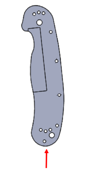
Figure 6: Drop test orientation for the knife scale.
Material Properties and Loading Conditions
Material: Formlabs Tough
Yield Strength: 34.7 MPa
Modulus: 1.7 GPa
Density: 1.15 kg/m^3
Drop height: 1 m
FEA Results
The simulation results below depict the maximum stress experienced by the scale during the drop test. The below figures demonstrate how the scales do not exceed the yield strength and thus do not experience failure. The redesigned scale experiences a lower maximum stress which validates the design changes from a structural standpoint.
|
Unmodified scale:
Figures 7 and 8: FEA results for the unmodified scale showing 13.5 MPa experienced which below 34.7 MPa yield strength.
Modified scale:
Figures 9 and 10: FEA results for the redesigned scale showing 11.2 MPa experienced which is below 34.7 MPa yield strength and even lower than original design.
|
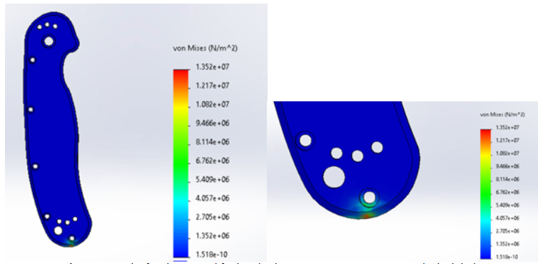
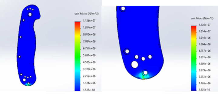
Table 2: Summary of FEA results for the original and redesigned scales.
| Scale Design | Max Stress on Impact [MPa] | Max Stress as Percent of Yield Stress |
| Original | 13.5 | 39% |
| Redesign | 11.2 | 32% |
Limitations of FEA
These results only account for the dropping of a single scale on the ground. In actuality, the scales will be affixed to a metal lock, liner, and blade. On one hand, the liner will provide more strength. On the other hand, the blade will make the total object heavier and increase mass and thus impact velocity. These considerations reduce the fidelity of the simulations but can only be addressed if a model of the entire knife and blade was made. For the final project, more in-depth simulations will be carried out to account for the entire knife assembly weight and its effect on stresses experienced on impact.
Validation of Finite Element Analysis
A rudimentary physical drop test was carried out with each scale to validate the finite element analysis results. Experiment conditions included a 1m drop height with each respective scale to match the simulation parameters. This experiment confirmed the outcome of our simulation results as none of the scales experienced impact failure.
Next Steps
Going forward the focus will be on running an SLA print trial on the current redesign and then possible iterations of the redesign if deemed necessary. Further simulations will also be carried out to more accurately represent the loading conditions during a drop test.