Overview
The design of this experiment involves a FFF machine used to create the parts and a 3-point bending test to test the strength of the parts. For the 3-point bending test we will be using the test methods in the ASTM D790-17 Standard Test Methods for Flexural Properties of Unreinforced and Reinforced Plastics and Electrical Insulating Materials (Procedure B) [1]. This method recommends a strain rate of 0.1%/min and expects failure at around 5% strain. The 3 point bending test works by slowly increasing the force on the part to maintain that 0.1%/min strain rate. To speed up the trials, as 16 parts need to be tested, the strain rate was sped up to 1 %/min. The machine used for the Proposal Update was the Netzsch DMA Eplexor which has a 500N load cell and a 3.0mm elongation sensor. This test method involved a static load sweep. This indicates that the load begins at 0 N and increases to a set value, in this case 400 N was the maximum force. Depending on the part thickness and material, a larger scale machine might be necessary to get the parts to fail. The loading for the parts can be seen in Figure 1. The material that was used in the FFF process was Polyethylene terephthalate glycol, PETG. Inputting the part geometry into the Netzsch machine, the software is able to provide a stress-strain curve from the data. From this curve the Ultimate Tensile Strength and Young’s Modulus can be found. For each trial the ultimate strength and Young’s modulus will be compared and a regression analysis will be performed on the data to find which aspects of the design have the biggest impact on part strength.
Dimensions of Part
The dimensions of the sample are intended to create a rectangular prism that is ideal for fitting into a 3-point bending test machine. Two attempts were made with varied cross sections in order to achieve a part that fails appropriately under this loading case. Figure 1 shows the two test samples that have been fabricated so far.
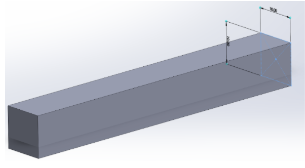
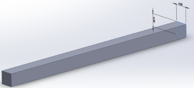
Figure 1: CAD renderings of the first two test sample geometries.
Preliminary Work
We first used the larger part with a cross section that was 10mm in height and width, with the strain rate of 0.1%/min recommended by the ASTM standard. This rate, combined with the thick part, did not achieve any useful data as there was no real strain produced. The second test was on the smaller part of dimensions 4.5mm in height and width with a faster rate of 1%/min. This gave more useful data, but the part never actually reached fracture because it’s too ductile. Once the force applied reached 99.93N (stress of 30.89MPa), the part kept yielding at the maximum force around 96N. When the stress was removed, there was clear plastic deformation on the part.
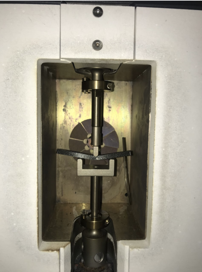
Figure 2: Image of part during the 3-point bending test.
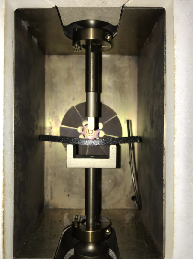
Figure 3: Image of part after test has been concluded.
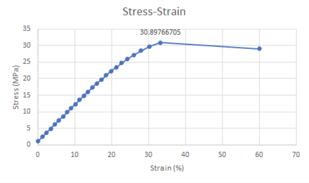
Figure 4: Stress-Strain curve from Netzsch machine.
Preliminary discussion
The material in this cross sectional area is not brittle enough to fracture. It reaches an ultimate tensile strength around 31 MPa, near 33% strain; however, the ASTM method prescribes the part to fracture near 5% strain, far less than the strain we found from our tests. To achieve this, we can do a few things. Adjusting the geometry of the sample can increase rigidity which will decrease deflection.
- In all practical cases, adding force until the part yields will qualify as a part failure. Increasing the force would require stress in the ballpark of 20-60 MPa according to literature of similar experiments for PETG. With the machine we currently have, we will not be able to reach the necessary force for fracture and therefore will not be able to properly test the parts to fracture.
- Making the part proportionally wider and taller will allow us to have a sharper bend to show failure in the part.
- We can change materials altogether to a more brittle material that will fracture within the 500N load that this DMA can apply.
Next steps
- Print another geometry that has a height that is in between our two shapes (7.5mm). The larger part didn’t yield at all because it’s too thick, and the smaller part just yielded too easily and never got to fracture. Also, make the depth wider to be more panel-shaped.
- Test new samples on the PEC DMA in attempt to yield until fracture.
- If fracture is not attainable, move to the DMA in the soft materials lab, where we can apply larger loads.
The next iteration of the sample does not have a square cross section. It is 15mm wide and 7.5mm tall. We believe this part will have structural properties that allow the test machine to fracture the part at a reasonable load. Figure 6 shows a rendering of this model.
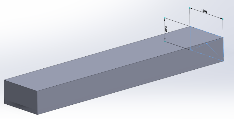
Figure 5: CAD rendering of newest test sample.
References
[1] ASTM International. D790-17 Standard Test Methods for Flexural Properties of Unreinforced and Reinforced Plastics and Electrical Insulating Materials. West Conshohocken, PA; ASTM International, 2017. doi: https://doi.org/10.1520/D0790-17