First Print Trial
For our first print trial, it was important to determine if the resolution of the printer would be sufficient for our small components, as well as understand the viability of 3D printing springs. In addition, we were able to determine more appropriate tolerances by examining how freely individual components were able to move when the entire lock and key system was assembled. The combined print time for the lock system was 5.25 hours, and 2.5 hours for the spring. Figure 1.1 shows all the printed parts of the first print trial before they were assembled, with a side-by-side comparison of the CAD used to create them.
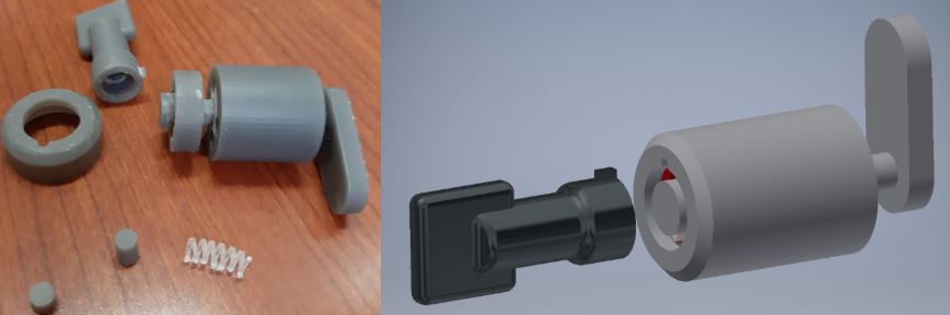
Figure 1.1&1.2. First print trial (left). CAD assembly (right).
Once the components of the lock and key system were assembled, an analysis of each of the individual components was done and the findings are summarized below.
Lock Component 1 – Cap
AM Method: SLA
Material: Grey Pro
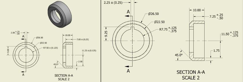
Figure 2.1&2.2. Original dimensions for Lock 1 – Cap (left). Updated dimensions with added tolerance (right). Units in [mm].
For the cap, the depth of the part needed to be increased to close all the way with the body. Also, the notch at the top needed to be enlarged to allow some room to shrink so that the notch on the key still fits.
Lock Component 2 – Body
AM Method: SLA
Material: Grey Pro
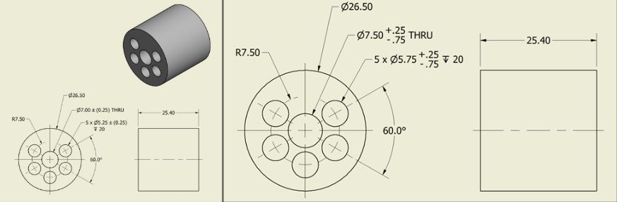
Figure 3.1&3.2. Original dimensions for Lock 2 – Body (left). Updated dimensions with added tolerance (right). Units in [mm].
The holes on the body of the lock were slightly too small for the pins, spring, and latch part, so all the diameters needed to be increased slightly to account for the shrinkage that can occur during production.
Lock Component 3 – Cylinders and Latch
AM Method: SLA
Material: Grey Pro 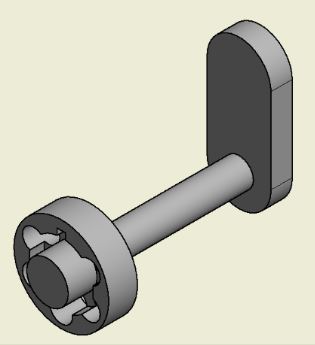
Figure 4. Original Latch with the cylinder opening.
The biggest issue with the cylinders and latch component was that it needed to be broken up into two parts for the second print trial. In addition, the tolerances needed to be adjusted since the shrinking that occurred was more than expected. The diameters of the cylinders increased 2mm and the diameter of the center extrusion decreased by 3mm.
Key
AM Method: SLA
Material: Grey Pro 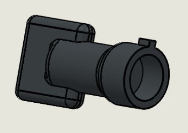
Figure 5. Key that will be used to open the lock.
The diameter of the hole in the middle of the key needed to be enlarged by about 1 mm to fit over the center of the latch. Furthermore, the notch at the top was made thinner to fit into the notch on the lock after shrinking.
Springs
AM Method: SLA
Material: Elastic
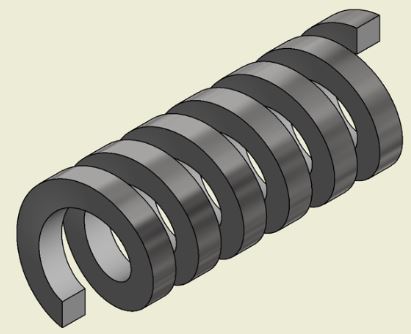
Figure 6. Original design of the spring.
The first print trial of the springs was printed with Formlabs Elastic material, but the spring was not strong enough to provide any significant force to the pins. For the second print trial, the team decided to examine material changes to spring properties before doing a major geometric design change to the springs.
Second Print Trial
After analysis of the first print trial, new springs with different materials and a new lock assembly was printed. The print times were 5 hours for the lock assembly, 0.5 hours for a spring printed with Flexible80A, and 1.25 hours for a spring printed with Durable.
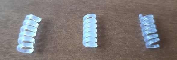
Figure 7. Original spring with the two reprinted ones.
Elastic (left), Durable (center), Flexible80A (right).
The second print trial for the spring was printed with Formlabs Flexible80A and Durable. Durable was the best, but still not strong enough. Moving forward, we will continue to experiment with material choices, but the design and the dimension of the spring may need to change as well.
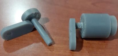
Figure 8. The Reprinted latch (left) and original
latch design (right).
In the first print trial, the original latch design was a single piece. This meant that in order to assemble to lock it had to be cut in half and then glued together. In the second trial, the latch and cylinders were split into two pieces, which will allow for them to be assembled without cutting anything and then glued up more uniformly. To take this even further, the parts could be designed such that no adhesive needs to be used and then the lock can be disassembled without damage.
Future Trials and Improvements
The results of the spring prints highlighted the need for further development of the spring design. Second round prints, done in Formlabs Flexible80A and Durable did not meet the stiffness requirements for the mechanism. With emphasis placed on stiffness instead of ductility and durability, Formlabs Tough 1500 has been selected for testing in the next round of prints. In conjunction with the material change, geometry changes will also be necessary to meet the mechanism requirements.
One solution to increase stiffness in a spring is to increase the diameter of the wire. It may also help to decrease the outer diameter of the spring. An additional way to make adjustments to strength is to vary the number of coils in the spring, and therefore the pitch between the coils, assuming the resting length of the spring remains. These design changes are well known to vary the strength for metal springs, but future print trials can help us determine if similar principles will hold true for 3D printed springs as well. Overall, we believe material choice will have the greatest impact on the viability of using a 3D printed spring in our lock and key system.
In the case that we are unable to get the 3D printed springs to function properly with further trials, we have also sourced appropriately sized metal springs from McMaster Carr. Although use of these metal springs is a last resort for the completed project, it allows us to test a working lock assembly while development of the spring continues.

Figure 9. Metal Springs sourced from McMaster-Carr