By: Jack Fahy, Gunnar Maples, Evan Ogren
Summary of Update
This update covers the CAD files and printing parameters used. The progress on a numerical simulation of the mechanical properties of the parts is discussed. The aluminum core is made and the physical parts are fatigue tested. The update concludes with a preview of work to come.
Prints
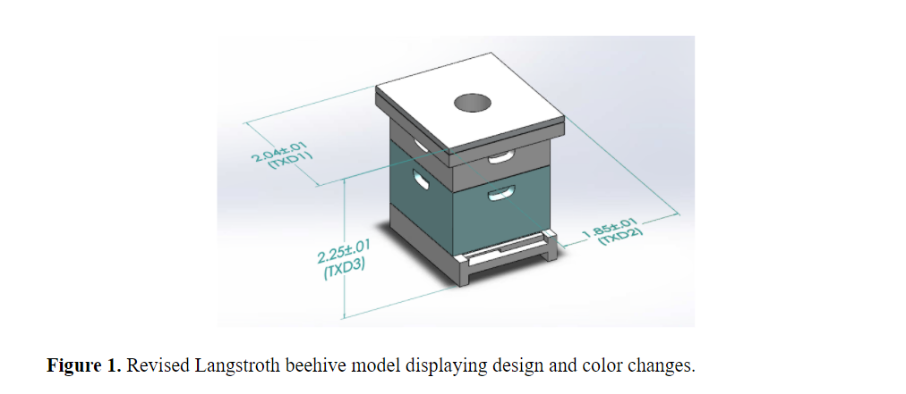
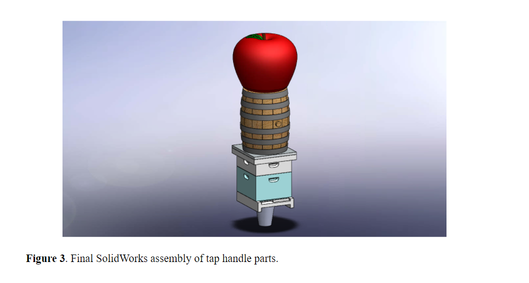
The client, Walker Fanning, gave the team feedback on the design after the initial SolidWorks models were developed for the apple, barrel, and Langstroth beehive. Adjustments were primarily made to the beehive’s aesthetic to make it more representative of typical Langstroth beehives. This included making the bottom box slightly larger than the top box and adding a slot that bees use for entering and exiting the hive as seen in Figure 1. The barrel model was simplified by reducing the number of planks (Figure 2). No changes were made to the apple model. Colors were also adjusted according to our client’s feedback, and the final assembly can be seen in Figure 3.
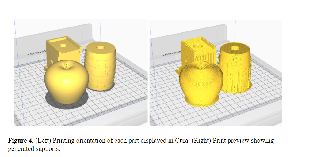
FFF printing was chosen as the printing method because of its simplicity, fast print time, and more readily painted material choices than SLA. Cura was used to determine printing time and decide on print parameters. The initial approach was to print each part separately at 0.1 mm layer height and 20% infill without support structure in order to preserve visual integrity and obtain a smooth surface finish. However, the barrel and beehive models produced significant print times exceeding 12 hours each. Thus, iterations were conducted by scaling the models and adjusting the infill and layer height parameters. After consulting with the client, the team decided to scale down the total height of our tap handle from 8.4” to 7”. After these changes, the LxWxH of each part was as follows: Apple (2.5”x2.5”x2.25”), Barrel (1.92”x1.92”x2.5”), and Langstroth beehive (2.04”x1.85”x2.25”). Even with these sizing changes, and adjusting the layer height to 0.2 mm, print times still exceeded the 8 hour limit. As the aesthetic and finish of the part surfaces is vital to this project, the team moved forward with this final iteration to avoid further reductions to part quality. Although a 0.2 mm layer height produces a rougher surface finish than 0.1 mm, the team deemed that sanding of the part surfaces would be sufficient to ensure a smooth finish. The 3 parts were printed simultaneously on one Ultimaker S3 printer (Figure 4) at the UW-Madison Makerspace with printing parameters of 0.2 mm layer height, 20% infill, and 0.4 mm nozzle. The shell thickness was designated as 0.8 mm thick (2 nozzle diameters). Parts were printed in white Ultimaker PLA with supports and adhesion. PLA was chosen because it has adequate material strength, can produce fine details, and can be readily painted with acrylic paints. The total print time was 9 hours and 55 minutes and the amount of material required was 141 grams. The print was successful on the first attempt and part quality was better than expected. The printed parts are imaged in Figure 5.

Simulation
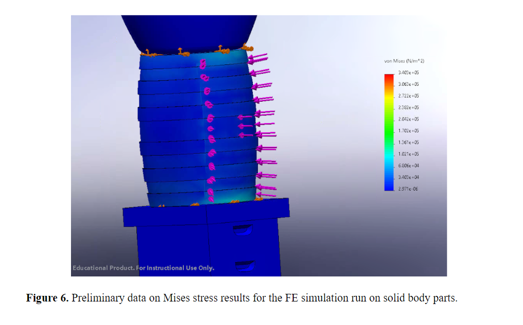
To determine the stresses that might be present in the tap handle under loading, a finite element (FE) simulation was conducted on the tap handle assembly in SolidWorks. There is no pre-existing PLA material model in SolidWorks, so a custom PLA material was created using mechanical properties found from various online sources [1,2]. For simplicity, the material type assumed was linear elastic isotropic (though we know this to be incorrect as 3D printed PLA is anisotropic). Fixed surfaces were prescribed at the ferrule base and at the interfaces between parts. A 20 lb load was distributed over a surface on the barrel representative of a hand pulling the handle. This load was selected because it is the standard load used for testing tap handles in industry. The simulation was then conducted and von Mises stress, equivalent strain, displacement, and factor of safety were assessed for the model.
The infill structure in the printed parts would be extremely difficult to model and possibly lead to erroneous values due to the complex geometry. The solution the team developed was to model a shelled material and a solid material as the team assumed the performance of a semi-filled material would fall between these two conditions. The simulation will be conducted for the tap handle with both solid body parts and shell parts with wall thickness equal to the printing wall thickness of 0.8 mm. At the time of this update, the loading boundary conditions of the analysis are still in development. The final result will provide a range of stresses values that the actual part loading will lie within. Figure 6 shows an example of one of the color map results obtained from the simulation. An analysis of these results will be included in the final report.
Experiment
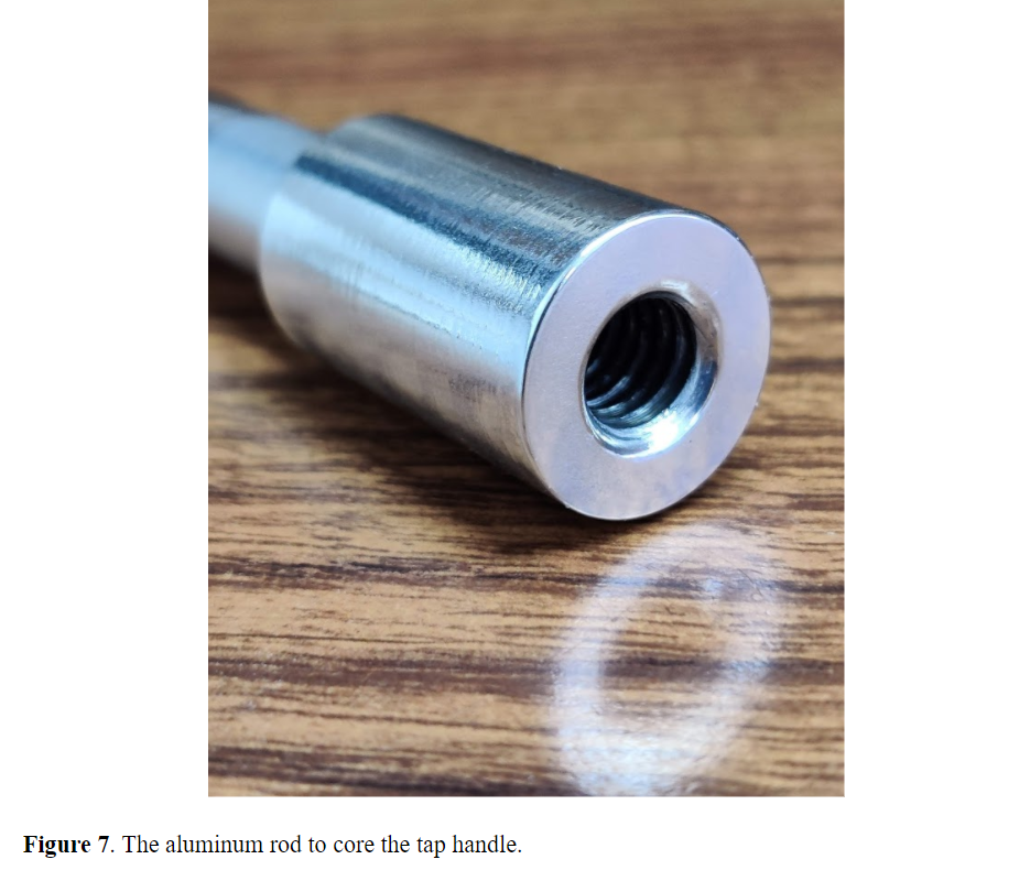
In addition to printing the parts, an aluminum rod was turned on a lathe and tapped into a tap handle. The rod was sized for a loose fit in a 0.48” hole. The parts were printed with a 0.5” diameter hole but the holes shrunk in printing. 1” of ?-16 threads were tapped into the rod. The fit portion is 5.625” long with a diameter of 0.47” and the visible portion is 1.25” long with a diameter of 0.75”. The rod was filed and polished to be safe to handle and visually appealing. The rod is pictured in Figure 7.
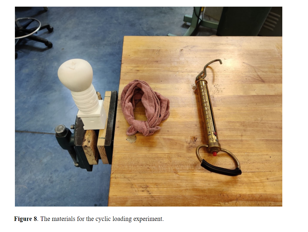
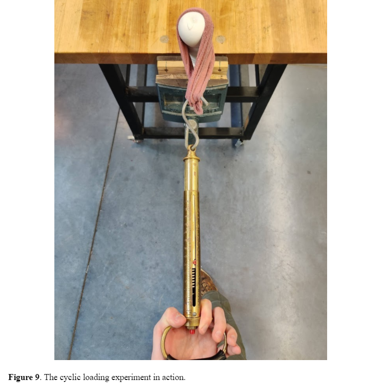
The printed parts and rod were assembled without epoxy to test the structure against the industry’s standard cyclic loading requirement. As noted in the project proposal, Dave Kaplan, the vice-president of engineering at Taphandles, tests his tap handles with 20lbs of force loaded 50 times perpendicular to the column’s axis to create bending and compressive stresses. The test on the printed parts was carried out with a spring scale and rag with the materials pictured in Figure 8. The rod’s base was fixed in a soft-jaw vise. The rag was wrapped around the top two prints to simulate a hand grasp with the scale pulling on the rag. By choosing the top two prints, the bending stresses cycled were the highest possible. The scale was pulled 50 times to the 20lbs mark on the scale. The test in action is seen in Figure 9. No deformation in the prints or rod was noticed, therefore the design passed the industry standard.
Next Steps
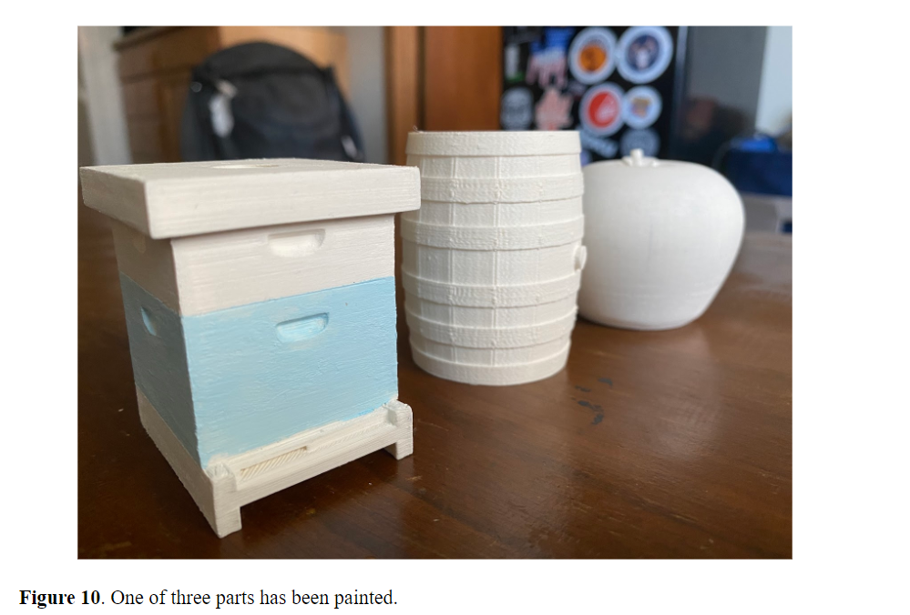
In the coming weeks, each printed part will first be sanded to smooth out any surface imperfections from the FFF process. Then, each part will be painted with a base coat of white before painting to their final colors, shown in Figure 3 of the assembly. So far one part has been painted, shown in Figure 10 below. After finishing the painting process and confirming the final look with our client, we will be epoxying the printed parts to the aluminum rod. Once the parts are fixed on the rod, we will be spraying all three printed parts with a layer of clear coat to give a smooth, glossy finish, and to protect the paint from chipping. Finally, analysis of the simulation results will need to be conducted to evaluate the validity of the model and the strength of our tap handle.
References
[1] S. Farah, D. Anderson and R. Langer, “Physical and mechanical properties of PLA, and their functions in widespread applications — A comprehensive review”, Advanced Drug Delivery Reviews, vol. 107, pp. 367-392, 2016. Available: 10.1016/j.addr.2016.06.012.
[2] “MatWeb – The Online Materials Information Resource”, Matweb.com, 2021. [Online]. Available: http://www.matweb.com/search/DataSheet.aspx?MatGUID=ab96a4c0655c4018a8785ac4031b9278&ckck=1. [Accessed: 06- Apr- 2021]