Project Update
Changes In Scope
In the project proposal, the molding material suggested was “Rigid” resin produced by Formlabs. However, the resin was changed from “Rigid” to “Clear” so there could be more transparency in the mold. This transparency is more favorable than the “Rigid” resin’s stiffness because the mold is not going to be under stress during the casting process, so a more rigid resin is not necessary. In addition, two FFF cylinder walls were printed from PLA filament to yield a wider range of surface roughness for this study.
First Trial Prints
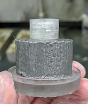
For our first print trial, an SLA printed assembly was created with a 50-micron layer height as seen in Figure 1. The nominal dimension of the inner cylinder is 0.5” and the inner diameter of the outer cylinder wall is 1.5”. A sample cast with this mold can be seen in Figure 2.
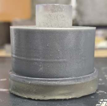
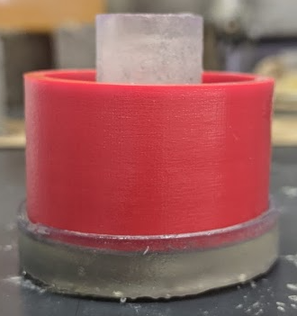
For comparison, two identical cylinder walls were created for the mold using PLA filament from an FFF machine with layer heights of 0.1 and 0.06 mm. The 0.06- and 0.1-mm layer height parts were printed in silver and red and can be seen in Figures 3 and 4, respectively. These additional cylinder walls were printed to compare the impact of layer height on the surface roughness of the fuel rods.
The hypothesis is for the surface roughness of the fuel rods to increase with the surface roughness of the mold. To validate this hypothesis, an Alicona Infinite Focus machine was used to find the surface roughness of each cylindrical SLA/FFF part and of two fuel rods. This information is summarized in Table 1.
| Part | Color | Layer Height | Print Time [hrs] | Mold Surface Roughness [micron] | Fuel Rod Surface Roughness [micron] |
| SLA (fine) | Clear | 50 micron | 3.25 | 1.15 | 26.36 |
| FFF (fine) | Red | 0.1 mm | 2.5 | TBD | 17.85 |
| FFF (very fine) | Silver | 0.06 mm | 4.25 | 12.85 | TBD |
As seen in Table 1, the surface roughness of the fuel rod did not correspond to the mold surface roughness as expected. One explanation for this could be that the oil used to lubricate the inner cylinder walls of the mold is more effective with the FFF parts. This is because with a higher surface roughness, the oil clings to cylindrical walls more due to the increase friction. On the other hand, the SLA printed part has a smoother finish, allowing the oil to run down the side of the cylinder to the bottom of the fuel rod. This results in less residual oil present to aid in the removal of the fuel rod from the mold.
In addition, the FFF “fine” print’s surface finish was not determinable with the Alicona due to the high reflectivity of the red filament used in the part but the “very fine” silver part was measurable. Although the surface roughness of the red mold used to produce the fuel rod is unknown, the surface roughness is thought to increase because the “very fine” FFF part’s surface roughness is still 10x higher than that of the SLA part.
Future Work
The next development in this project will be to cast the remaining fuel rod for the very fine FFF silver mold, and to recast the previous molds without oil. Surface roughness measurements will be retaken, with the goal of reducing the presence of confounding variables by eliminating the use of oil in the mold removal. In addition, the “fine” FFF part will be reprinted with a different filament color in hopes of gaining measurements of surface roughness.