Project Overview
As a reminder of our project, our team is working towards the end goal of manufacturing a hydrofoil using additive manufacturing methods. The hydrofoil is designed to be used in combination with a personal surfboard.
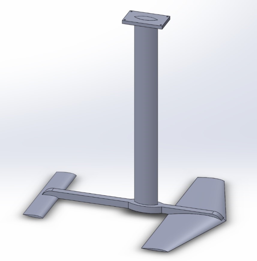 Figure 1: First design of our hydrofoil.
As seen in Figure 1 (copied from our project proposal), we have a lot of interlocking parts with several challenges. First, many of the parts are too long to be printed in one piece. This means that they must be printed in several interlocking sections. Second, we want all the parts to have thin cross-sections for maximum aerodynamic efficiency. This creates challenges when designing parts that must be stiff and strong. Related to aerodynamics, the surface finish of the parts should be smooth to maintain laminar flow over the foils.
Testing Plans
To test all these problems, we had to come up with a simple experiment. Because the time and cost to print a full assembly with multiple variations would be huge, a method to test on a smaller scale was needed. To do this, we decided to take the cross-section of the full-size mast and extrude it 8 inches, with a joint in the middle. This would be a small enough part that several variations could be tested while using a minimum amount of print time. With these experimental parts, we could then strength test the shape, joint type, material, print orientation, and infill. They would also serve as a test for surface roughness.
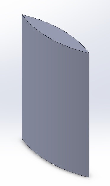 Figure 2: Base cross-section shape for the test pieces.
The first idea proposed is derived from woodworking- where joints are commonly made between pieces by using interlocking shapes. The chosen woodworking-type joint for this test is a mortise and tenon- shown in Figures 3 and 4.
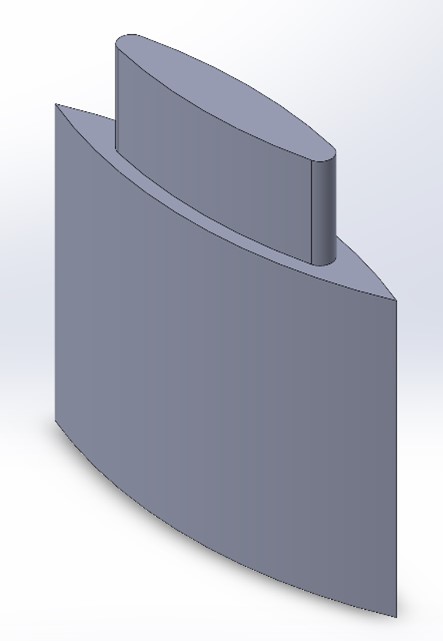 Figure 3: Tenon joint.
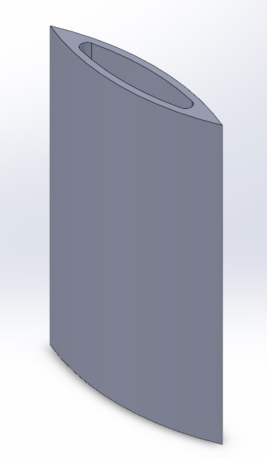 Figure 4: Mortise joint.
These two parts were designed to be a total length of 8 inches when assembled. The parts would ideally slide together easily and JB Weld Epoxy would be applied inside the joint for maximum strength.
The second idea is to use metal ‘ribs’ inside the plastic mast. Two variations of this idea were tested: one large hole in the center of the mast (Figure 5) and four small holes organized in a square (Figure 6).
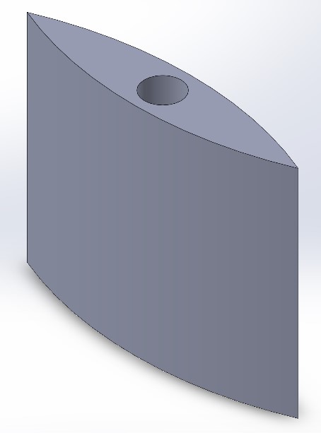 Figure 5: Single through-hole with a 0.5-inch diameter.
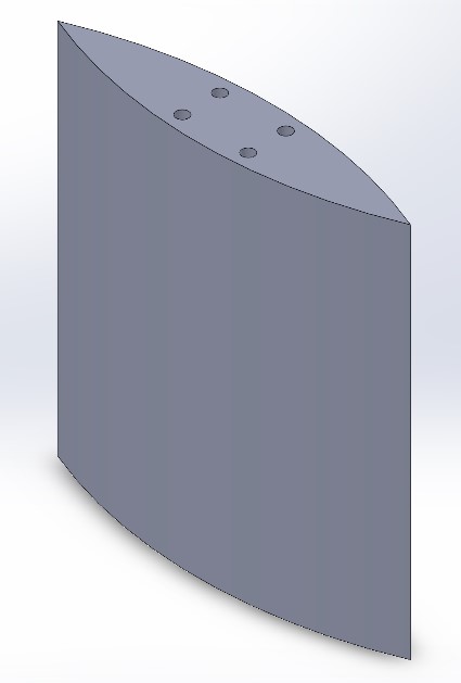 Figure 6: Four through holes with 0.125-inch diameters.
Again, like the mortise and tenon joint test, two of each design were printed so that they could be assembled into 8-inch-long lengths. These metal-rib designs would be joined by sliding the round metal stock into each piece with JB Weld and allowed to cure. The expected advantage of the metal rib designs over the mortise and tenon joint is increased stiffness and strength for no added print time and very little extra cost. The strength is essential to the durability of the hydrofoil assembly, and the stiffness is important to its use; when riding a surf hydrofoil, the mast should be rigid to maximize responsiveness and give the rider a high degree of stability and control. The single-though-hole design is expected to be stronger but heavier than the four-through-hole design.
Choice of material for the metal ribs was based on available materials in the Team Lab: ASTM A36 Steel, ASTM A108 Steel, 303 Stainless Steel, and 6061-T6511 Aluminum. We chose to use stainless steel for its’ corrosion resistance and high stiffness per volume. Stainless steel is chosen over aluminum because the size of the cross-section is more important than weight. With that constraint, stainless steel is the best choice.
Manufacturing
Again, like the mortise and tenon joint test, two of each design were printed so that they could be assembled into 8-inch-long lengths. These metal-rib designs would be joined by sliding the round metal stock into each piece with JB Weld and allowed to cure. The expected advantage of the metal rib designs over the mortise and tenon joint is increased stiffness and strength for no added print time and very little extra cost. The strength is essential to the durability of the hydrofoil assembly, and the stiffness is important to its use; when riding a surf hydrofoil, the mast should be rigid to maximize responsiveness and give the rider a high degree of stability and control. The single-though-hole design is expected to be stronger but heavier than the four-through-hole design.
Choice of material for the metal ribs was based on available materials in the Team Lab: ASTM A36 Steel, ASTM A108 Steel, 303 Stainless Steel, and 6061-T6511 Aluminum. We chose to use stainless steel for its’ corrosion resistance and high stiffness per volume. Stainless steel is chosen over aluminum because the size of the cross-section is more important than weight. With that constraint, stainless steel is the best choice.
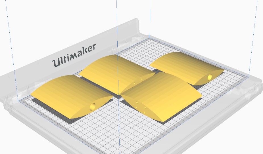 Figure 7: Print orientation shown in the Cura software.
With this orientation, the print time for each 4-inch section was 5 hours and 10 minutes (varying slightly with each design). With 6 total 4-inch sections, that gave a total print time of 31 hours so far in our project. We printed all 4 rib-design parts in one print as shown in Figure 7 and the mortise and tenon parts in another print.
The other print parameters were chosen to minimize print time: default profile of 0.2 and infill of 20%. Pictures of the print for the two steel-ribbed designs are shown below.
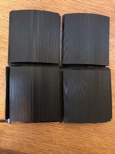 Figure 8: Top view of the print.
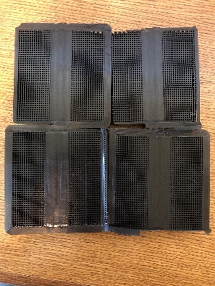 Figure 9: Bottom view of the print. Support material can be seen.
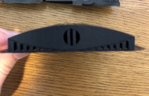 Figure 10: Side view of the printed part. Support inside the hole can be seen.
As seen in Figure 10, due to the print orientation, there was support material inside the holes. This took extra time to remove and was especially difficult in the very small holes of the 4-ribbed design. After removing the support material, we cut the stainless-steel rods to length and went to insert them into the parts. However, we realized that the holes had not been oversized enough to allow easy insertion of the rods. With some heat and a tap hammer, we were able to insert the rods. For these reasons, the metal-rib design took much longer to assemble than the mortise and tenon joint, which required pliers to remove the supports and filing to clear out the remaining material. However, the assembly time could be greatly reduced with holes that have a larger clearance around the rods.
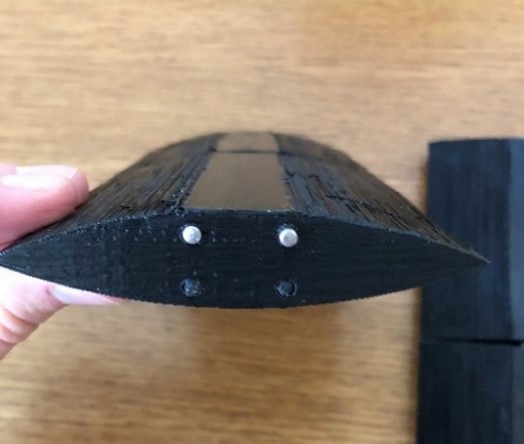 Figure 11: Four 0.125″ rods inserted with JB Weld.
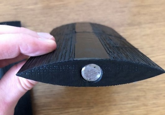 Figure 12: One 0.5″ rod inserted with JB Weld.
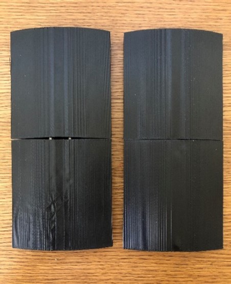 Figure 13: Top view of assembled metal-rod designs.
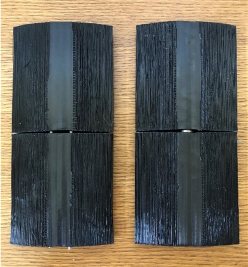 Figure 14: Bottom view of assembled metal-rod designs.
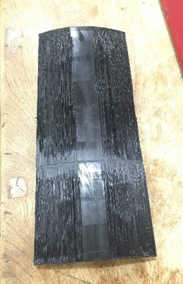 Figure 15: Bottom view of assembled mortise and tenon joint.
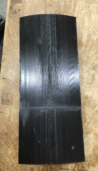 Figure 16: Top view of assembled mortise and tenon joint.
One disadvantage of the print orientation used is the poor surface finish. As seen in Figures 14 and 15, the surface finish on the bottom of the parts was very poor because the material was trying to print on top of the support material. The top sides also had a ‘stepped’ finish which is not as bad as the bottom side, but still undesirable.
Testing
To test the strength of our parts, we performed a 3-point bending test at the machines in the 307 lab of Engineering Hall. A span of 6 inches was used to accommodate our 8-inch-long parts. This test gave us force vs deflection data which we could then use to analyze the strength of the designs, the plastic, and the printing parameters. Specifically, we are interested in the overall Young’s Modulus of each part.
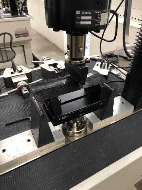 Figure 17: Three-point bending test of the mast.
The data taken is shown in the plot in Figure 18. Note that we performed two tests on the 0.5” rod design to see whether the second test would give a similar force vs deflection shape.
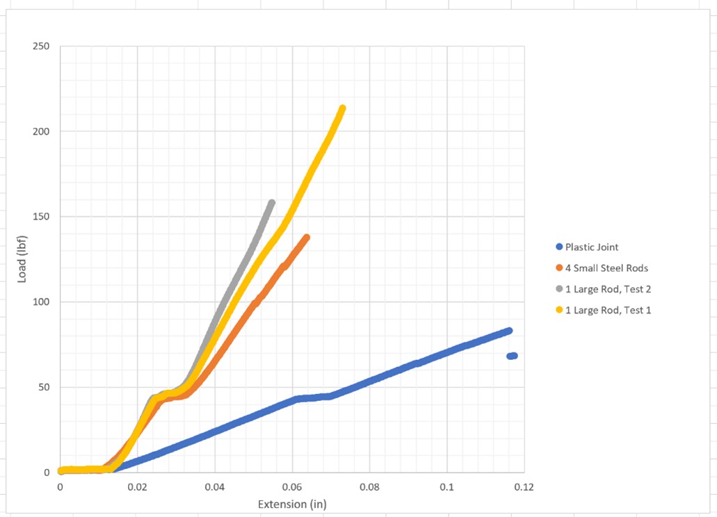 Figure 18: Force vs load raw data for each part.
The data in Figure 18 shows that the 0.5” rod design is the stiffest, the 4-rod design is slightly less stiff, and the plastic joint is the least stiff. All three designs withstood 80 pounds or more without showing any indication of failure. The small break in force at roughly 50 pounds in each design is believed to be related to local failure of the wall or infill at the location of supports.
Calculations
To obtain the Young’s Modulus of each design, we used the following equation. Delta_max is the maximum displacement, P is the applied load, L is the length of span, E is the Young’s Modulus, and I is the area moment of inertia.
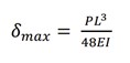 Figure 19: Equation for 3-point beam bending.
The load and deflection data are known, the span length is known, and area moment of inertia can be calculated in SolidWorks. With that information, we solved for the Young’s Modulus for each design.
Because the prototype is comprised of a long thin mast, buckling is the primary strength concern in the final design. To test this issue, a simple, analytical model was created using the Euler buckling formula to determine the critical load of the mast (full-size length of 30 inches).
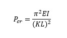 Figure 20: Euler’s buckling formula.
The values were input to Excel, and the desired values were calculated. The Excel table used is shown in Figure 21.
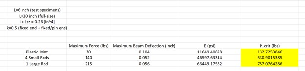 Figure 21: Excel table used to calculate critical loads for buckling.
Results
The values calculated in Figure 21 tell us that an all-plastic mast design will likely not be strong enough. Even if a stronger plastic and larger infill were used, a design with metal rods would be stronger and stiffer. The design with one rod is the best design because it is the strongest and easier to assemble than the 4-rod design. The critical load for buckling with a 0.5” stainless steel rod is 757 pounds. This is with a 30-inch-long mast. Assuming a rider weight of 160 pounds, this design (with the tested printing parameters) is predicted to be strong and stiff enough with a generous safety factor.
It is important to note that this is only a prediction. It is possible that stress or deflection is more critical than buckling. In this case, a model would have to be tested to failure- or in the real world- to ensure a viable design.
Wing Research
A separate area of research for our project is the airfoil shape. With the help of CAD and additive manufacturing, we can make the airfoil any shape that we want and customize it for the conditions. For our project, we will assume a rider weight of 160 lbs and a speed of 10 mph in water. With this information, we searched for an airfoil shape that would maximize stability and minimize drag.
Using dimensionless number equations and recommended sizes of foils in the market, we predict a front wing surface area of roughly 1200 cm^2. Because we do not wish to perform optimization techniques and CFD analysis to select our own foil shape, we will use NACA 1505. This shape is recommended by “PrfctChaos” on an online forum [1].
The NACA designation is a numerical code for the shape. We used an online airfoil plotting code to produce a visual of the shape [2], shown in Figure 22.
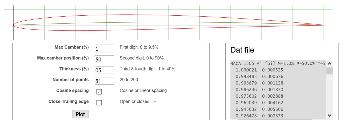 Figure 22: NACA 1505 shape, plotted using an online website.
Many other factors could be considered in the hydrofoil shape such as aspect ratio, tip curvature, angle of incidence, fuselage length, and mast height. For this project, we will not do any further research into these areas- we will use the NACA 1505 airfoil with a surface area of 1200 cm^2. All other shape parameters will be estimated from hydrofoils already in the market.
Conclusion
Through the first few phases of our research, we have learned some valuable lessons that we intend to apply to our final model. We have shown that it is possible to print our mast and other parts in sections that can be assembled. From our 3-point bending tests, we were able to determine the strength of each design. We found that while both joint options that include metal ribs are effective, the 0.5” rod proved to be the best suited for supporting the load of the rider if we were to create a full-sized hydrofoil. Our calculations for the 0.5” joint suggested that the mast would be able to support over 750 lbs., which will ensure a stiff mast for our 160-pound rider. One key issue we found through our testing is the surface finish of the 3D parts. When printed using the FFF printers, and with an orientation that was relatively flat on the build platform, we had difficulties maintaining a surface finish that would move through the water easily. Solutions for this problem will be further researched. With all this information, we are prepared to begin designs for the full assembly with an accurate wing shape and strong interlocking sections.
Next Steps
For the last section of our project, we hope to manufacture a full-size working model. To achieve this goal, a few challenges will need to be overcome: smoothing the surface finish, managing print time, and designing complex shapes.
Our initial prints have a layered finish on the top side and a very rough finish on the bottom side of the print. We will need to determine how to best fix this issue in our final parts. One possible solution is to print the parts standing up. This would create a grain that is parallel to the flow. However, this method would reduce strength in the most critical direction. Another option is to use a combination of sanding and body filler to smooth the surface.
The shape of the hydrofoil is complex and will require advanced modeling techniques. We believe this can be overcome with some of the advanced features available in Solidworks.
Since our prototype is large, print time will be an important consideration. Our test pieces have shown that print times can be kept below 8 hours with careful consideration of the printing parameters. However, we recognize that the volume of material needed may become cost-prohibitive. Cost and time predictions will be analyzed to determine if all components can be manufactured within the allotted time and budget. If not, we will print sections of our prototype to prove that it meets the constraints without a full prototype.
References
[1] “Wing profile info for backyard hydrofoil builders – Kiteforum.com.” https://kiteforum.com/viewtopic.php?t=2407467 (accessed Apr. 05, 2021).
[2] “NACA 4 digit airfoil generator (NACA 1505 AIRFOIL).” http://airfoiltools.com/airfoil/naca4digit?MNaca4DigitForm%5Bcamber%5D=1&MNaca4DigitForm%5Bposition%5D=50&MNaca4DigitForm%5Bthick%5D=05&MNaca4DigitForm%5BnumPoints%5D=81&MNaca4DigitForm%5BcosSpace%5D=0&MNaca4DigitForm%5BcosSpace%5D=1&MNaca4DigitForm%5BcloseTe%5D=0&yt0=Plot (accessed Apr. 05, 2021).