Project Overview
Optimization of a part can change many details of the design. We will be looking at the design of a bike saddle. We have inherited this project from a graduate student who is working with a bicycle company and the kinesiology department to optimize the bike saddle design. The goal is to make the saddle as light as possible while being comfortable to the rider. The printed saddle will be combined with reinforcement material so it will remain rigid under the force of the rider’s weight.
FEA Analysis
Thus far, our group has taken the time to create a variety of design iterations and run finite element analysis (FEA) on each of them to gain a better understanding of how each model would behave under various loading conditions. As far as which loading conditions were considered, a study performed by the department of kinesiology has found that people mainly tend to ride bicycles in one of two positions [1]. These are referred to as the “tops” position and the “drops” position and can be seen in Figure 1 below.
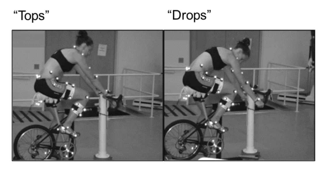
Figure 1: Bike riding positions
The combination of riding in these two positions leads to load points seen in our analysis in Figure 2, denoted by purple dots/arrows. Thus, when it came to testing the saddle model, these were the load points that were used. With the load points determined, the FEA was performed. In the below figures are laid out diagrams of how one particular bike saddle performed under load.
Figure 2 details how the bike seat deflected while subjected to the load conditions. As seen in the figure, the highest deflection occurred at the transition from the narrow to wide end of the seat. Given that this portion of the saddle has no reinforcement under it in the form of metal rails like the other ends have, it makes sense that the highest deflection is seen in this region. This high deflection can lead to potential failure in a bike seat. To make it less likely to fail under any given load, carbon fiber composite will be implemented.
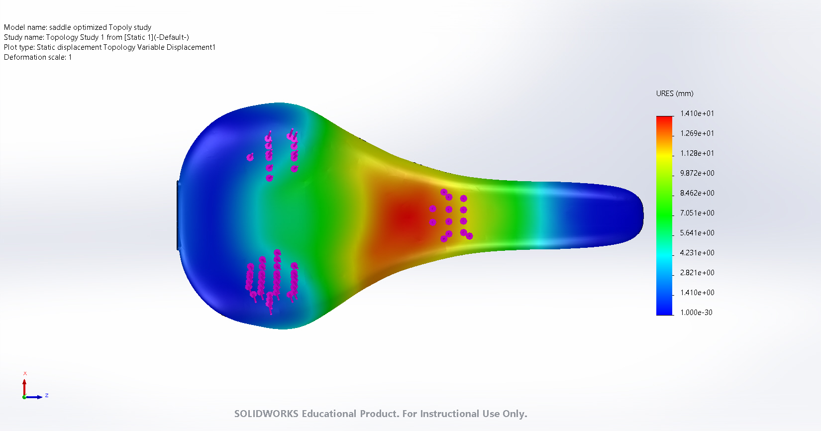
Figure 2: Design study of loaded saddle deflection.
Using the same load conditions, FEA was next conducted to determine strain locations within the saddle. This strain analysis can be seen in Figure 3. We found that, while there were no locations on the saddle that yielded incredibly high strain amounts, there were still some weak spots. The highest areas of strain occur mostly around the three load points. It is worth noting that the strain was not continuous throughout the saddle either. As seen in Figure 3, there are certain areas that do not have as high of a strain between the three load points.
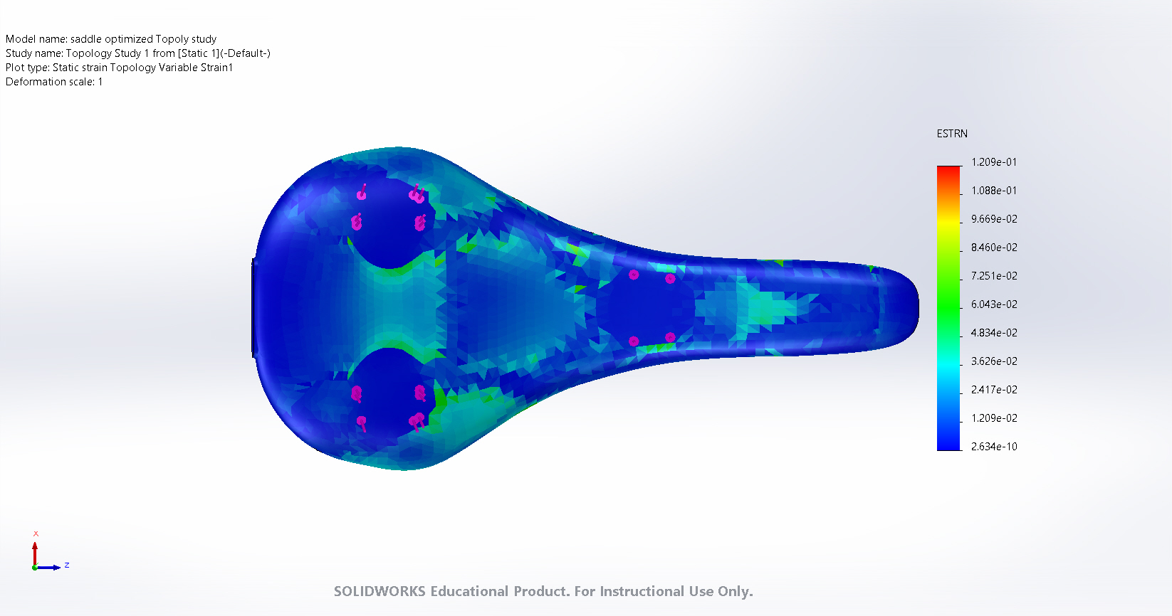
Figure 3: Design study of loaded saddle strain.
Topology Optimization
To maximize the performance of the bike saddle, we must both reduce the saddle weight and increase the saddle strength by intentionally implementing carbon fiber composite into our design. Through stress analysis of our SolidWorks model, we were able to identify the model’s high stress locations as seen in Figure 4.
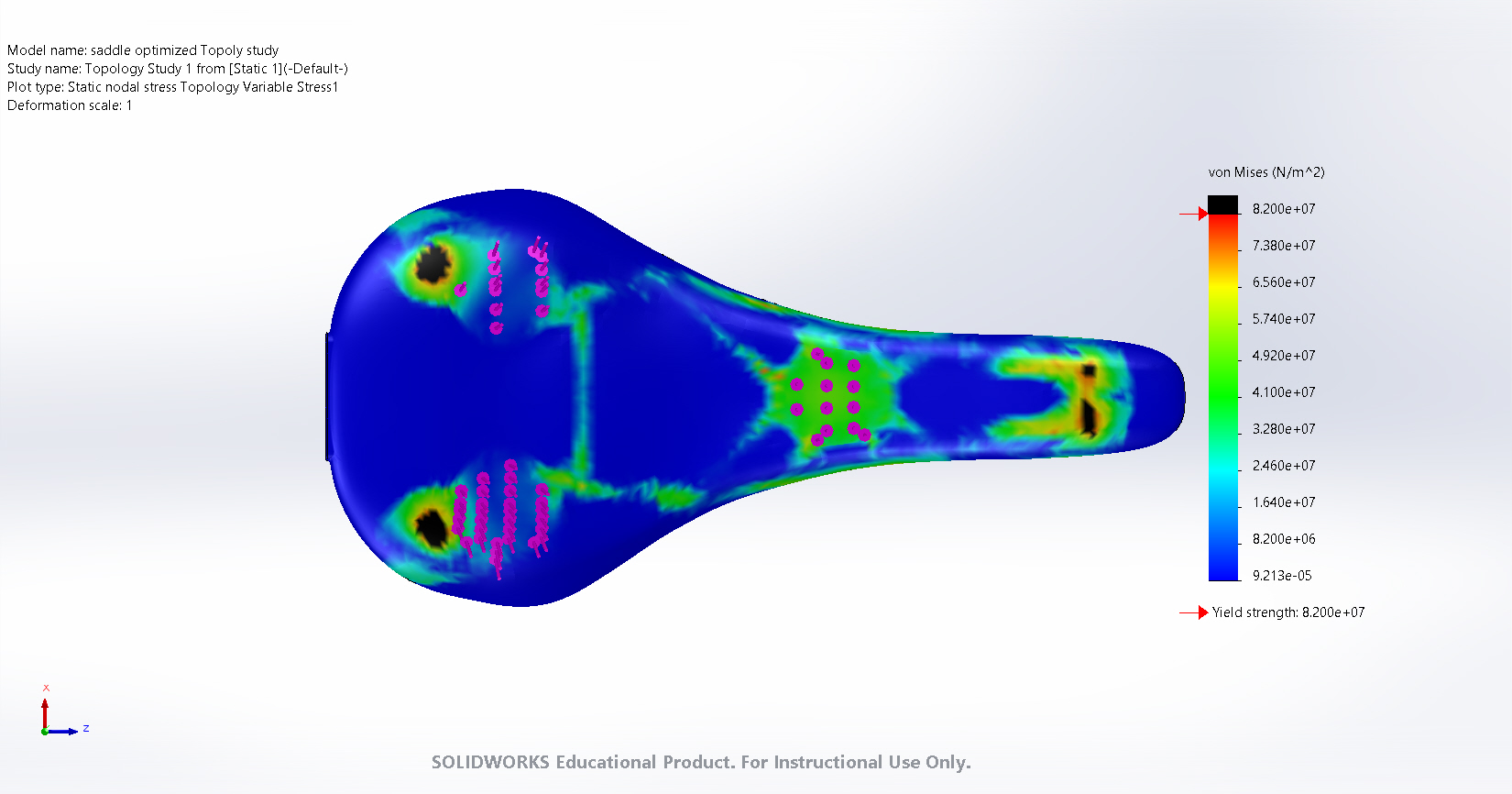
Figure 4: Design study of loaded saddle stress.
The use of topology optimization further allowed us to isolate these regions and create a framework for the areas of concern that necessitate composite reinforcement [2]. The topology optimization conducted in Figure 5 is a rough approximation of our ideal composite design and was run with a factor of safety constraint of 1.5.
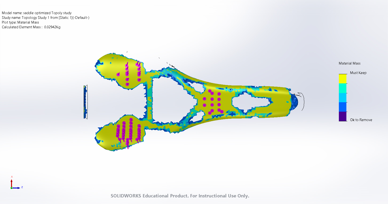
Figure 5: Topology optimization of loaded saddle.
The plan for this carbon fiber implementation will be that of a woven fabric design. In order to more accurately test these models moving forward, it’s imperative that we enter approximate values for yield strength and other mechanical properties into SolidWorks before the FEA. Through the help and advice of graduate student Alec Redmann, we know the yield strength to be around 130 GPa and a Poisson’s ratio of about 0.22 in the direction of the fibers. In the non-fiber direction, we find yield strengths around 10.3 GPa and a Poisson’s ratio around 0.3. In addition to the implementation of reinforcing composite, we also intend to reduce the volume of the epoxy material to reduce part mass. The topology optimization provides us a guideline for that as well since the voided regions are those at a lower stress which can thus have material removed.
Design Iteration Plan
To explore a variety of options and alternate designs, we will take the information we have gathered from our stress, strain, and deflection analysis to as well as the topology optimization to optimize our overall design. We intend to revise the topology optimization to simplify the composite material design for manufacturing. Additionally, we will create a few different models with optimized part mass and conduct stress, strain, and deflection design studies to assess how decreased part volume affects the strength of the saddle with our composite design. Through consultation with Alec Redmann, the graduate student who originally proposed the project, we will create a final design within the following weeks.
Manufacturing Plan
The manufacturing of our composite saddle is a multistep process with a DLS printer and carbon fiber prepreg as we described in our project proposal. The carbon fiber will be cut from prepeg to the design derived from our topology optimization and the saddle base will utilize the previous model constructed by Alec Redmann and his team with a minimized mass design we have yet to determine. As this process requires multiple machines and manufacturing processes, our final design will be completed by April 26th to ensure adequate time for machining and UV curing. All equipment necessary to manufacture the complete part will be supplied by the Polymer Engineering Center.
References
[1] Redmann, A. 2021. “3D Printed Hybrid Composite Structures – Design and Optimization of a Bike Saddle,” (accessed 6 April 2021).
[2] Finkelstein, A. 2021. “Harnessing the Power of Topology Studies in SolidWorks Simulation,” cati.com (accessed 5 April 2021). Available: https://www.cati.com/blog/2020/06/harnessing-the-power-of-topology-studies-in-solidworks-simulation-part-1/