Introduction
One of the most popular additive manufacturing processes is Fused Filament Fabrication, FFF. When parts are made using the FFF process the inside of the part is not completely solid. Based on user set parameters, the inside will vary. Such parameters include infill geometry, orientation, and infill percent as well as the number of wall layers. Each of these factors is expected to impact the bending strength of the part. In this test, a rectangular block will be put through a 3-point bending test to determine the parts bending strength. Each of the previously mentioned parameters will be varied to find how they impact strength. This project will help display how each parameter affects the strength to weight ratio. The easiest answer is to completely fill the block as this will be the strongest part, but as long as the strength maintains above an allowable limit, less material can be used. This project will help to optimize the FFF process by providing insight into how internal part geometry affects the strength of a part.
Preliminary Design and Manufacturing Choice
Figure 1 shows a design of a sample test piece in a simple rectangular block shape. The block is done using the FFF process. The dimensions of the block will not change for each test, but rather the infill of the block will change. The infill geometry, orientation, percentage, and wall thickness will be tested.
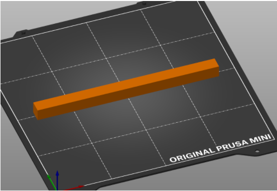
Figure 1: Design of sample piece.
Proposed First Print Trial
The first phase of this project is to print the samples on the Prusa Mini 3D printer. Since the prints aren’t expected to be challenging to print, we will print the initial 16 samples consecutively. This phase is expected to take one week after approval of this project proposal.
The second phase of the project is to subject each sample to a 3-point bend test. We chose this test to determine mechanical strength because it places the sample under a combination of tension, compression, and shear stresses; samples that perform the best in this test are expected to perform best in their real-world applications. Each sample of the same dimensions will be tested to failure to calculate maximum strength. This phase is expected to take longer due to availability of the machine, 3-4 weeks.
| Trial | Infill Geometry | Infill Orientation | Infill Percent | Wall Layers | ||||
| 3D Honeycomb | Rectilinear | Z | Normal to Z | 25 | 50 | 2 | 4 | |
| 1 | X | X | X | X | ||||
| 2 | X | X | X | X | ||||
| 3 | X | X | X | X | ||||
| 4 | X | X | X | X | ||||
| 5 | X | X | X | X | ||||
| 6 | X | X | X | X | ||||
| 7 | X | X | X | X | ||||
| 8 | X | X | X | X | ||||
| 9 | X | X | X | X | ||||
| 10 | X | X | X | X | ||||
| 11 | X | X | X | X | ||||
| 12 | X | X | X | X | ||||
| 13 | X | X | X | X | ||||
| 14 | X | X | X | X | ||||
| 15 | X | X | X | X | ||||
| 16 | X | X | X | X | ||||
Table 2: Chart displaying each combination tested
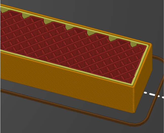
Figure 2: Cross section -Rectilinear, Z, 25%, 2 layers
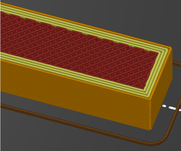
Figure 3: Cross Section – Rectilinear, Z, 50%, 4 layers
The photos above are a couple variations of parts that will undergo the 3 point bending tests.