3D Printed Airless Bicycle Tire
Jessica Lim, Sojin Kim, Ting-Chun Lee, Zhaohui Ma
Polymer Engineering Center, University of Wisconsin-Madison, USA
Abstract
The purpose of this project is to design and 3D print an airless bicycle tire. Fused Deposition Modeling (FDM) process is one of the most utilized Additive Manufacturing (AM) processes, gaining its popularity for its rapid prototyping and low fabrication cost. Thermoplastic polyurethane (TPU) was selected as the filament for tire printing due to its material properties closely resembling those of rubber. This report discusses the structural stability associated with the hexagonal shapes and the observation of the printed parts outcome.
Background
For more than 100 years, pneumatic tires have maintained complete dominance in the tire market for various applications including cars, bicycles, and more [1]. Nevertheless, as per pertinent data, the primary concern associated with pneumatic tires is air leakage [2]. Riding on a tire with low air pressure can lead to damage to the tire, inner tube, and rim. If the tire is flat, there’s a risk of it dislodging from the rim, potentially resulting in a crash [3].
Over the past few years, innovative tire technology has driven rapid growth in both the automotive and military sectors. Innovative tire technology, known as non-pneumatic tires (NPT), refers to tires that do not rely on air pressure for support [4]. One significant advantage of airless tires is their puncture-proof [2]. Airless tires eliminate the risk of flat tires caused by punctures from sharp objects such as nails, glass and also road hazards such as potholes, curbs, and other obstacles [5]. Another benefit of airless tires is their decreased maintenance needs and enhanced durability [6].
Airless tires are designed to mitigate the need for riders to address punctures, reducing the associated risk and allowing drivers to feel safe while driving on the road. Without the need of air in tires, this eliminates the necessity for pressure checks, making it ideal for self-driving vehicles [6]. Additionally, 3D printed tires will reduce the environmental footprint by reducing scraps and energy used in tire production [7].
Our goal of our project is to design and produce a 3D-printed airless bicycle tire. Our project will mainly focus on determining the design of airless bicycle tires, specifically shaping the structure of the inner tube and the material and 3D printer for the airless tire will be selected. In addition to this, the selected 3D printer will be used for fabrication, followed by testing the structural stability, focusing on shaping the inner tube structure.
Design
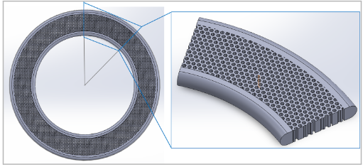
In our exploration of existing airless tire designs, we encountered a variety of innovative approaches suitable for different types of vehicles. The curve design (Figure 1(top)), predominantly seen in automobile tires, is engineered for durability and performance under the weight and speed conditions typical of car travel. Meanwhile, the circle design (Figure 1 (middle)), is utilized primarily for bicycle tires, catering to lighter loads and providing a balance between comfort and resilience on varied terrain. Lastly, our project introduced the hexagonal design (Figure 1(bottom)), developed specifically for airless bicycle tires. This new design focuses on optimizing weight distribution and shock absorption to enhance the cycling experience, reflecting a blend of traditional methods and cutting-edge adaptations.

We believe the hexagonal design is superior to other shapes for several reasons. Firstly, hexagonal structures are renowned for their enhanced mechanical properties. These honeycomb-like configurations excel in crashworthiness and energy absorption due to their unique geometric arrangement, which effectively dissipates energy during impacts [8]. Secondly, the interlocking nature of hexagonal structures increases the load-support stability of the tire, ensuring that airless tires can adequately absorb road shocks and maintain a stable, comfortable ride [9]. Additionally, hexagonal structures allow for efficient use of space and material. They tessellate perfectly, meaning they can cover a surface without any gaps or overlaps, which is ideal for compact and efficient designs [10]. Overall, this geometry is the most efficient shape for filling a plane with equal-sized cells using minimal material, thereby allowing for an even distribution of forces upon impact—a crucial factor for crashworthiness.
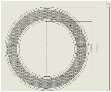
In the development of our airless bicycle tire design, we adhered closely to the standard dimensions of conventional road bike tires, specifically the 700 x 23c mm size. This dimension denotes a tire with an approximate diameter of 700mm and a width of 23mm (Figure 2). Our airless tire mirrors this size with an outer diameter of 700 mm and maintains the width at 23 mm. However, we have modified the inner diameter to 460 mm. This increase in the inner diameter is a strategic design choice to accommodate a larger number of hexagons within the tire structure, thereby enhancing its capacity for energy absorption and overall durability.
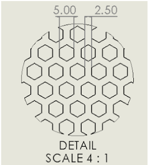
Our airless tire design utilizes a hexagonal structure to optimize performance. Each hexagon within the tire has a diameter of 5 mm (Figure 3). Initial testing with a 1 mm distance between hexagons revealed excessive deformation, impacting the tire’s integrity and performance. After several iterations, we found that a distance of 2.5 mm between hexagons offers a balanced solution. It significantly reduces deformation while keeping production costs manageable. This adjustment ensures that the tire maintains its shape and functionality under various conditions, providing a reliable and efficient alternative to traditional pneumatic tires. This design approach not only addresses the typical challenges associated with airless tires, such as increased rigidity and decreased shock absorption, but also capitalizes on the potential for lower maintenance and longer lifespan, making it an attractive option for road cyclists.
Material Choice
In the manufacturing of airless tires for bikes, the selection of the right elastomeric materials is crucial. These materials need to possess properties such as heat resistance, wear resistance, elasticity, durability, and vibration absorption.
Several elastomeric materials have been identified as ideal for bike tires. These include Ultra-High Density Ethylene Copolymer and Polyethylene Foams, which are used in the manufacturing of airless tires by companies like Air Fom which claims to maintain its physical properties from -30 C to 50C . They offer excellent vibration dampening and insulation properties, superb strength and tear resistance, and excellent shock absorption. Another material is either, a patented polymer nanofoam used by Tannus for their airless bike tires. It’s a micro closed-cell polymer resin material similar to what’s used in running shoes. However these materials are not suitable for additive manufacturing methods and are typically used in solid tubes for bike tires rather than having any type of structure.
The selected material for printing the airless tire is thermoplastic polyurethane (TPU), characterized by its properties as a thermoplastic elastomer with high elasticity and durability, making it well-suited for airless tire construction. TPU exhibits a combination of plastic and rubber properties, including high elongation and tensile strength, as well as resistance to abrasion. TPU has a Taber wear value of T0.35-0.5mg, which is the smallest among plastics. In addition TPU, particularly TPU 92 A has a shore hardness of 92, as well as a tensile yield strength of 15.6 MPa and an elongation at break of 550%. These values are comparable to those of natural rubber with shore hardnesses of up to 95, tensile strength of 28 MPa, and elongation between 300-900%.
Additive Manufacturing Method
The chosen method for the additive manufacturing process employed in the fabrication of the tire is Fused Deposition Modeling (FDM). The advantages associated with an FDM printer encompasses cost-effectiveness and rapid printing capabilities. The project aimed to employ the Stratasys F370 printer, accessible at the UW Makerspace, for the fabrication of the airless tire. However, owing to a hardware malfunction of the Stratasys F370 printer during a test print (further elaborated in the Results section), an alternative FDM printer, the Bambu Lab printer, was utilized. The filament used with the Stratasys F370 and Bambu Lab printers were TPU 92A and TPU 95A, respectively.
Test Prints
Print One
The first test print of the airless bicycle tire entailed producing a scaled-down model of the dimension of a standard bicycle tire (Figure 4). This decision was necessitated by the limited dimensions of the Stratasys F370 print bed, measuring 355mm x 254mm x 355mm. The scaled-down model had an outer diameter of 110mm, an inner diameter of 60mm, and a thickness of 5mm. Printing this model required five hours. Subsequent to printing, the fabricated part underwent immersion in an organic solvent bath to eliminate the water-soluble QSR support surrounding it, a process lasting 12 hours. Following the solvent bath, the part was immersed in clean water for an additional 12 hours to purge any residual solvent. The total cost incurred for this initial print amounted to $7.69.
Upon the conclusion of printing, it was determined that the scaled-down model was unsuitable for part testing owing to the hexagonal pattern’s width-to-diameter ratio surrounding the tire. The hexagons’ diameter was excessively broad, resulting in significant deformation under compression force.
Furthermore, the model’s narrow width posed challenges in maintaining balance on a flat surface during compression testing. Consequently, it was determined that the subsequent print should be produced to scale, with adjustments made to the size and density of the hexagons.
Print Two
The second test print of the airless bicycle tire was produced at one-eighth of the dimensions of a standard bicycle tire (Figure 5), ensuring compatibility of the part fitting with the printer’s print bed. However, the printing process was interrupted (Figure 6) by a jammed print head on the Stratasys F370 printer. Furthermore, the UW Makerspace was depleted of FDM TPU 92A filament required for the Stratasys printer. The estimated total print time for the complete print was estimated to be 80 hours, incurring a total cost of $105.37.
Print Three
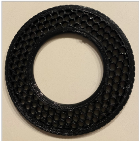
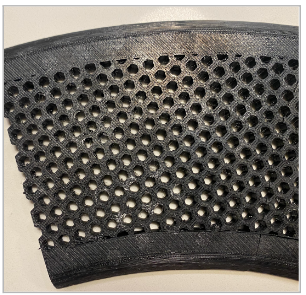
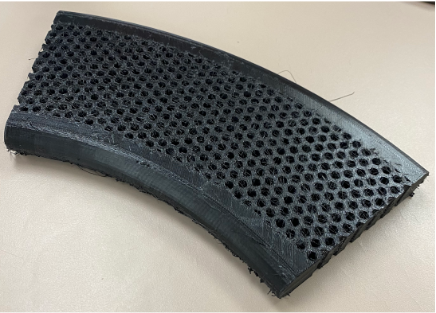
The third test print of the airless bicycle tire was printed with the identical model dimensions as the second test print (Figure 7). The Bambu Lab printer was used for this iteration. The resultant printed part featured PLA support structures situated beneath the printed model. The support structures are removable through physical and manual post-processing methods. The total printing time was 50 hours, with a total cost of $24.26.
Discussion
The TPU filaments employed in both printers demonstrate distinct melt flow indices (MFI), the measure of the fluidity of thermoplastic material when melted under applied pressure and temperature [11], thereby influencing the printing duration. TPU 95A features an MFI of 36.5±2.6g/10min [12], whereas TPU 92A possesses an MFI of 21g/10min [13]. Consequently, utilizing TPU 92A on the Stratasys F370 printer extends the printing duration by approximately one additional day compared to the Bambu Lab printer employing TPU 95A filament.
Results and Testing
The focus of testing for the tire sections was on the mechanical properties of the material and structure. In order to understand the testing methodology that should be used, it is first important to understand the mechanical loading on a standard bike wheel. As seen in Figure XX,
the load on a tire is typically applied evenly on the two sides of a bike wheel through two forks that attach to the hub or center of the wheel. When a bike is ridden, the weight of the rider and the bike itself is transferred to the ground through the tires. This weight or load is distributed evenly across the contact patch, the area of the tire that is in direct contact with the ground.
The load on the tire causes the sidewalls of the tire to compress. This compression decreases the pressure inside the bottom part of the tire, which in turn increases the pressure at the top. This pressure difference stretches the sidewalls and generates tension in them. The air inside the tire doesn’t carry any load. Instead, the load is carried by the tension in the sidewalls and the spokes of the wheel. The spokes, which connect the hub of the wheel to the rim, work in tension to support the load and maintain the round shape of the wheel. This results in a load distribution similar to that seen in Figure XX, where force experienced by the contact patch results in a local
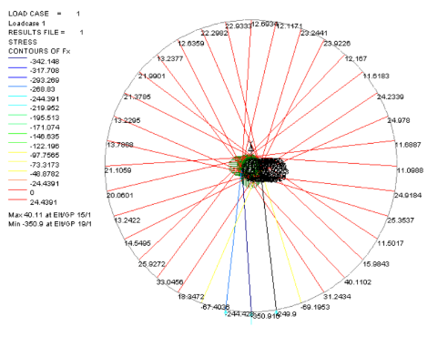
compressive force at the bottom of sections of the spokes and tire, while a smaller tension force is experienced by the rest of the tire due to the spokes “pulling” the forces to the hub.
What the loading distribution shows is that the greatest magnitude of localized forces experienced by the bike tire is when it is in compression, and thus the deformation of the tire during this compressive loading will have the greatest influence on the comfort of the rider. Because of this, it was decided that testing on the tire sections would be done with a compression machine, in which the deformation of the printed structures would be measured under an increasing compressive load. Two different parts were tested, the first being a small rectangular section of the tire internal structure printed on the Stratasys F370 and the second part being the curved section representing ? of a typical 700 x 23cc wheel printed on the Bambu X1 Carbon printer.
The Stratasys print was loaded vertically in the compression machine as observed in FigureXX. The section of the print was cut to have straight edges touching both the top and bottom plates of the machine to normalize the load. A uniform rate of deformation was then 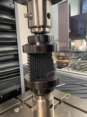
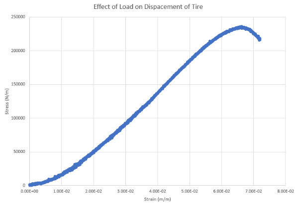
applied to the test section. In order for the data to be comparable to that of an entire wheel, both the load and deformation were normalized over the area. The load was divided by the area of the cross section touching the compression plates, and the deformation was normalized by the height of the part being compressed to produce strain. The normalized stress vs strain curve can be characterized largely by a linear relationship, with the amount of stress needed per unit of deformation being largely consistent throughout. It was noted that after a strain of around 6.5%, the load needed for further deformation begins to decrease. Under observation, the cause of this was that the part began to buckle and collapse towards the side, rather than any permanent deformation being done to the structure of the part itself.
The second test that was conducted was with the curved section of the tire printed with the Bambu X1 Carbon printer. Due to the curvature in the part being unable to maintain significant surface area contact with the two compression plates, it was decided that a metal rod would be used as a proxy to maintain a consistent contact area as seen in figure___. Similar to the
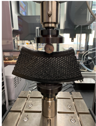
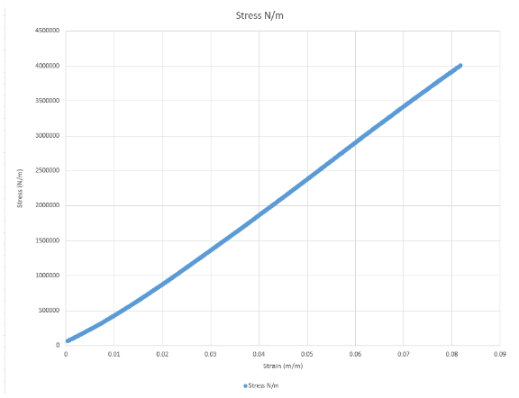
previous test, a uniform deformation rate was applied to the part as the top compression plate moves downward, with the loading being normalized by the area under the rod in contact with the part, and the deformation being normalized by the height of the part underneath the rod. Once again, the deformation of the part structure appears to have a linear relationship with the load put on the part. No buckling was observed in this section due to the thickness being significantly larger than that of the previous part. It was noted that the deformation in this part was strictly local underneath the rod in which the load was applied, rather than deforming the entire structure, this means that the structure is not as efficient at distributing vibrations across the entire tire. This test was concluded after a stress of 400,000 N/m^2 was applied and no permanent deformations were observed.
In the case of both the tested parts, it was evident that the applied loads only caused deformations within the elastic regime, with no permanent deformations in the plastic regime. The rate of recovery for both parts was also relatively fast, recovering to its initial size within a second after the load was removed. It can also be said that the strain rates observed were not significantly larger than those seen with a pneumatic tire. Figure XX shows displacement vs force for a pneumatic tire. 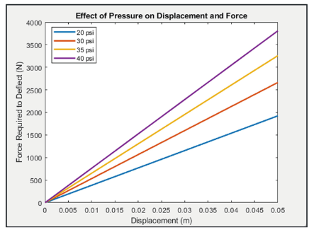
Given that the size of a typical pneumatic tire is around 700 mm in total diameter, a displacement of 0.05 is roughly a strain rate of 0.07, similar to those observed in the tests conducted on the sample parts. It can be concluded that under normal use conditions, that is accounted for the load of the bike frame and a rider, the deformations experienced by the non-pneumatic tire will significantly impact the comfort of the rider.
This report presents a comprehensive overview of the design, material selection, and testing of a 3D-printed airless bicycle tire with a hexagonal structure. The primary objective was to develop a puncture-proof and low-maintenance alternative to traditional pneumatic tires. While the report presents promising initial findings, further investigations are necessary to address the remaining challenges and uncertainties, such as issues involving heat dissipation due to friction in the tires and rough surface finish during initial prints. Possible future work that is planned include evaluating the tire’s ability to dissipate heat generated during use is crucial, as excessive heat buildup can compromise the material’s properties and lead to premature failure. It would also be interesting to explore the use of fiber reinforced TPU filaments could potentially enhance the structural integrity and impact resistance of the tire, mitigating the issues of buckling and localized deformation which were observed during the compression tests. It will also be beneficial to conduct tests with full-scale tire models and assessing the ride quality under various road conditions will provide valuable insights into the tire’s performance and potential improvements needed for a comfortable riding experience, as it was noted during testing that comparing sections of a tire will never be a direct comparison to that of a whole. Finally, it will also be imperative to resolve the printing challenges encountered, such as the jammed print head and filament availability, as well as finding methods to provide a smoother surface finish.
Reference
- Sandberg, U. (2020). The Airless Tire: Will this Revolutionary Concept be the Tire of the Future? Modern Concepts in Material Science, 3(3).
- Deng, Y., Wang, Z., Shen, H., Gong, J., & Xiao, Z. (2023). A comprehensive review on non-pneumatic tyre research. Materials & Design, 227, 111742. https://doi.org/10.1016/j.matdes.2023.111742
- Lawyers, F. K. I. (2023, October 25). Understanding the dangers of flat tires. South Florida Injury Attorneys Blog. https://www.southfloridainjuryattorneysblog.com/understanding-the-dangers-of-flat-tires/
- Kucewicz, M., Baranowski, P., & Ma?achowski, J. (2017). Airless tire conceptions modeling and simulations. In Lecture notes in mechanical engineering (pp. 293–301). https://doi.org/10.1007/978-3-319-50938-9_30
- What every cyclist should know about flat tires. (n.d.). https://www.sheldonbrown.com/flats.html
- Manibaalan, C. (2013). STATIC ANALYSIS OF AIRLESS TYRES. International Journal of Scientific and Research Publications, 3(8). http://www.ijsrp.org/research-paper-0813/ijsrp-p2084.pdf
- Shahpasand, R., Talebian, A., & Mishra, S. (2023). Investigating environmental and economic impacts of the 3D printing technology on supply chains: The case of tire production. Journal of Cleaner Production, 390, 135917. https://doi.org/10.1016/j.jclepro.2023.135917
- Wang, Zg., Shi, C., Ding, Ss. et al. Crashworthiness of innovative hexagonal honeycomb-like structures subjected to out-of-plane compression. J. Cent. South Univ. 27, 621–628 (2020). https://doi.org/10.1007/s11771-020-4321-2
- Roets, A. (2022, January 21). Design: What airless tires show engineers about a material switch – Engineering Institute of Technology. Engineering Institute of Technology. https://www.eit.edu.au/design-what-airless-tires-show-engineers-about-a-material-switch/
- Leanza, S., Wu, S., Dai, J., and Zhao, R. R. (June 21, 2022). “Hexagonal Ring Origami Assemblies: Foldable Functional Structures With Extreme Packing.” ASME. J. Appl. Mech. August 2022; 89(8): 081003. https://doi.org/10.1115/1.4054693
- Bremner, T., Rudin, A. and Cook, D.G. (1990), Melt flow index values and molecular weight distributions of commercial thermoplastics. J. Appl. Polym. Sci., 41: 1617-1627. https://doi.org/10.1002/app.1990.070410721
- TPU 95A HF. Bambu Lab, https://us.store.bambulab.com/products/tpu-95a-hf (accessed 01 May 2024).
- FDM TPU 92A. Stratasys, https://www.stratasys.com/en/materials/materials-catalog/fdm-materials/tpu-92a/ (accessed 01 May 2024).