Initial Approach and Clock Face
The clock mechanism we found online, has had varying reviews of success. Because of this we decided to print the clock via FFF using PLA as the material. After our initial print we then would decide what print trials and experiments are necessary. After our first print, we realized there were two problems. The first being the surface finish of the base of the clock. As seen in Figure 1, the front of the base which was lying on the build plate does not have a smooth looking finish. There are white marks showing that the face was being built upon a textured plate.

Figure 1: The textured plate of the FFF printer created some markings on the front face of our clock. Additionally, leftover residue remained as pictured by the fingerprints at the top of the piece. However, after some cleaning the face looked better, but still had some imperfections.
After consulting with the staff at the makerspace it was determined that there is not another way to improve the finish on the face of the clock. Flipping the part over for another print would add unnecessary supports and potential blemishes to the backside, as seen in Figure 2.
The simple solution will be to lightly sand the face to get rid of any blemishes. The face of the clock was on its own build plate and took two hours to complete.

Figure 2: The backside of the face contains the housing for the actual clock mechanism on top, as well as holes to screw in the gears that help drive the hour gear around the clock. Because it was not face down on the build plate it came out looking great.
Gear Printing Trouble
The second and more concerning problem was the thread resolution of the gears and their fasteners. The FFF printers at the makerspace do not have enough resolution to accurately print threads that can screw together. We have two potential ways to go about fixing this issue. The first way would be to increase the size of the threads and attach them to the dowel on the backside of the gear via glue. The second and more straightforward way would be to redesign the gears to be solid and use taps and dies to create the desired threads. For either solution we will have to convert the STL files into solidworks part files in order to properly edit them. As we have done our research, turning an STL file back into an editable CAD model is very difficult. We are currently trying to find a work around, so we can put our own threads on the gears.
Additionally, another test we are currently printing is trying a stronger material to print the gears. Instead of using traditional PLA, we are using Onyx filament which contains nylon and chopped up carbon fibers. The change in material will provide us gears that will be much more wear resistant when compared to PLA, and hopefully the stronger material and different printer will result in higher quality threads. The print time for all of the gears took about two and a half hours.
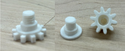
Figure 3: The threads printed on the driving gears did not have enough resolution to thread together. The focus of our next experiments will be on remedying this issue.

Figure 4: The hour indicator and the minutes indicator printed with high quality for one exception. Just like above the threads on the minutes indicator are not high enough quality to be fastened. However, the numbers and spurs on each are printed very well.
Moving Forward
After our second trial print of gears gets done, we will have to make a decision on the proper modifications to get the gears in working order. The solution could include printing on a different printer, using a new material, or a redesign of the gears themselves. The driving clock mechanism has been ordered and is on its way. Once we receive it we will be able to tell if the gears are strong enough to drive the clock for a full day.