Project Outline
After the preliminary design of the laptop stand was created, we discussed updates we want to make to reach our final goal. For the first design only two legs of different sizes were printed, although we will be using four legs in the final design; we did not want to have duplicates of the legs because we knew we wanted to make some changes. Some of the main changes we are going to include will be adding some resin caps for the feet and a resin sleeve for the shelf that prevents the laptop from sliding off. We used FFF additive manufacturing for the preliminary design because it did not need any post processing techniques and was a similar strength to SLA. The clearances of the pins in the legs will not need to be adjusted. Overall, the preliminary design of the laptop stand will set us up for success in creating our final product.
Prototype Print Trial
CAD Models of Print Trial:
Figure 1. Isometric View of Full Assembly
Figures 2.a. / 2.b. Isometric View and Side View of a the front leg assembly
Figures 3.a / 3.b. Isometric View of pin and lock assembly and close up view of the tooth and slot mechanism
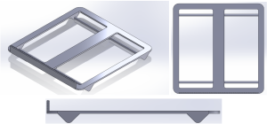
Figures 4.a. / 4.b. / 4.c. Isometric View, Side View, and Top View of the laptop plate
Printed Prototypes:
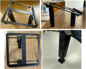
Figures 5.a / 5.b / 5.c / 5.d Front View, Side View, Isometric View, and Leg Isolation of Print
Positive Outcomes of Print Trial:
Overall, the print trial was a success. Most of the concepts behind our laptop stand design proved valid when printed using FFF techniques with PLA as the material of choice. The design of the legs worked well, with the telescopic leg and pin system functioning as designed, allowing the leg height to be easily adjusted through the position of the pin. Additionally, the foot pieces on the bottom of the legs had a snug fit with the bottom leg pieces. Another positive is the snap fit of the top piece of the legs onto the rod of the laptop plate. The open slot at the top of the legs slides over the horizontal rod with reasonable force, requiring no tools, and only a small push with one hand while the other hand holds the plate. Once together, the plate will not easily separate from the legs unless the same intentional force is used, preventing accidental separation of the assembly.
Material Use:
From the project proposal, we had discussed the use of SLA rather than FFF. We had decided to use FFF for the initial print as it was faster and not the end use product. After considering our design, we will continue to use FFF as the method and main material for the laptop stand as it has a higher strength. To mitigate slipping of the legs on smooth surfaces and the laptop on the stand, we plan to use SLA. This would be either flexible resin or elastic resin. These added parts are further discussed in the redesigns and future trials.
Table 1: Amount of printing time each part took in the FFF machines within the Makerspace.
| Part (# of prints) | Time |
| Top Plate (1) | 13 hours |
| Top Leg Pieces (2), Bottom Leg Pieces (2), Foot Pieces (2), Pins (2), Pin Locks (2) | 4 hours, 1 build plate for all pieces |
Areas of Concern:
The main aspect of our design that we want to work on is that the legs and stand aren’t as stable as we’d like. The leg pieces have too large a clearance between them, leading to instability and wobbling. This problem worsens as you extend the legs to be taller, and the legs become very unsteady. As well, the flat part of the stand is loosely attached to the legs, causing more shifting once the stand is assembled. Although the legs snap around the plate rod nicely, the rod is too loose once it is inside the leg housing, allowing for too much movement in the connection. The pin locking mechanism also has similar issues to the leg and plate snap fit issue. The tooth and slot design of the mate proved conceptually valid, but the dimensions of the features were too small for the resolution of the printer, resulting in inaccurate printing of the geometry. Another area to work on is how best to orient the prints or to change the design of the plate and outer leg pieces to reduce supports, or make removing supports easier.
Redesigns and Future Trials
Design Revisions for Prototype:
While our team has printed once, many iterations of designs have been considered. The print most closely resembles what our final product will look like with some added parts. These revisions aim to maximize strength and stability to ensure laptop safety.
One revision our team plans to make includes minimizing the clearance between the legs. The adjustable legs have parts that slide inside of them to utilize custom height with pin holes. These components that fit inside the leg itself cause room for instability as the clearance is quite large. We plan to minimize this to have a more snug fit while still sliding in and out of the leg easily for less side to side movement within each leg. The next issue we saw after the print was that the base of the legs were not sturdy enough to resist changing angles of the legs as they are free to spin along the bar they clip on to. Since we like how customizable the stand is, we want to keep the clip and bar method and will simply enlarge the base that the legs stand on. Another concern we saw was while adjusting the location of the legs and clipping them in place, the bar they attach to could be more durable. To ensure this, we will make the bars thicker along with adjusting the leg clearance to match that of the bars so they can still clip in place. With the legs being able to rotate about the bars, this causes instability and likelihood of one of the legs spinning out and not providing structural support for the laptop on the stand. To change this, we will be adding bars to the bottom of the legs so the front and back legs on either side respectively are adjoined and cannot rotate unless rotating together. We will also create an option for a square base by creating pins along the center point of these bars and another bar with holes to respectively hold in place orthogonal to the two bars holding the front and back legs together. This would fully constrain the base and create optimal security but would also be removable if the user so decides.
Printing Revisions for Prototype:
Our revisions for printing will include using the SLA Formlabs 3D printer with the elastic material. There are only a few parts we will create using the elastic material, but it will ultimately help the overall functionality. The elastic material will be used specifically for the caps and sleeve to prevent sliding. The tolerance on the pins will need to be updated since the parts were too small for the printer, which caused issues on the surface finish. We also plan to revise the design to eliminate support materials to aid in the post processing of the prints.
New Ideas for Prototype Models and Materials:
For our updated prints and experiments, we are planning to add a few pieces to our design to reduce slipping. Firstly, we will add caps to the feet of the stand, made of flexible resin to hopefully attain a more rubber-like surface. These will be printed using the Formlabs SLA printers in the Makerspace, using their flexible resin. Ideally, these will be able to fit around the ends of the legs and fit securely with a small clearance. We are also considering adding a resin layer in the divots in the tops of the legs to reduce sliding between the legs and the plate. This might not be necessary, however, if adding rods connecting the legs solves this problem.
Future Plans:
The next steps in our project include making these alterations and revisions, printing each part with the decided method of FFF or SLA, and creating the additions discussed above. With these changes we will have a final print to evaluate.


