Project Change Overview and Summary
Our group’s initial proposal was a 3D printed heat exchanger, for increasing the efficiency of a glass furnace, made of a material with a high melting temperature such as steel and titanium. After contacting the Alloy Design and Development Lab it was determined that a print of any size would be prohibitively expensive, and our group had to pivot our project.
Our group chose to keep our project related to glass blowing equipment, using additive manufacturing to produce optic molds more efficiently. Optic molds are a useful tool for glass work. They have an inward facing pattern and are used to add optical effects on glass by blowing a bubble of glass inside of them. By printing these molds through PLA, encasing them in plaster and then casting them in aluminum, precise and cost-effective optic molds may be created. Our team will prove this by creating and testing such a mold.
Glass Blowing Optic Molds
As shown, optic molds are one-piece molds that have an interior pattern and an open top that allows a bubble of glass to be placed inside and then blown, to leave the pattern’s impression on the glass. The glassblower then works the glass, being careful to not reheat the piece to the point at which it loses the surface pattern. Additionally, colored rods can be placed in the notches of these molds which would melt into the surface of the bubble and produce a striping effect.


Figure One: Optic Mold in Use Figure Two: Several Optic Molds


Figures Three & Four: Glasses produced with Optic Molds
PLA Print
The design of the optic mold was drafted in 3D using SolidWorks and can be seen in Figure Five. This CAD file was printed in PLA to cast a plaster mold. PLA was the ideal choice as it can be burned away leaving the mold intact. The negative mold was used to cast the aluminum to produce the final optic mold.
A Unimaker FDM printer with transparent filament was used with a 5% infill and 0.1 mm layer distance. The print took 19 hours and 25 minutes to complete due to the fineness of the layers, which contributes to the surface finish of the molds. A 5% infill was chosen so that less plastic would need to be burned away, while providing enough structure so that the print would be successful without support material. Transparent filament was chosen since it has less dye than colored plastic. This was a consideration because dyes cannot be burned off, and so their residue on the mold would lead to an undesirable surface.


Figure Five: Multiple Views of Blow Mold CAD

Figure Six: PLA Printed Part
Plaster Mold
The plaster was formed around the printed part, to produce a mold suitable for casting. After baking the water out of the plaster, the printed part is then burned away, leaving only the plaster casting mold. The ability to burn away the PLA was necessary due to the taper of the inside and outside, as well as the foot which served as a sprue. At some point during these processes a hairline crack formed in the mold, but since the surface finish and integrity was restored by using hose clamps, it was deemed usable for the aluminum pour.
Aluminum Casting
Aluminum was cast in the plaster mold and allowed to cool, forming the final optic mold. Before Melting the aluminum, the plaster mold was placed in an annealer set to 1100F to roughly match the temperature of the aluminum and reduce thermal shock. Then, A graphite crucible was placed in the furnace and allowed heat until to turning orange (See Figures Seven and Eight). Using an infrared thermometer, the heat of the crucible was measured to be around 1500F and scrap casting aluminum was placed inside. Once melted, the plaster mold was removed from the annealer and aluminum was poured into the sprue, mostly filling the mold cavity. The mold was not completely filled because liquid aluminum leaked through the cracks. Once the aluminum solidified and more aluminum was melted, a second pour successfully filled the rest of the mold and it was allowed to cool. This process can be seen in Figures Nine and Ten.
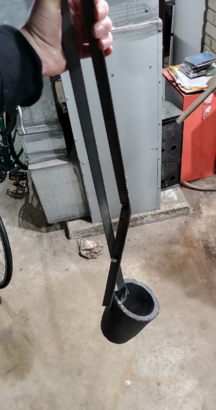
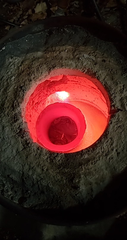
Figure Seven: Crucible Figure Eight: Heated Crucible
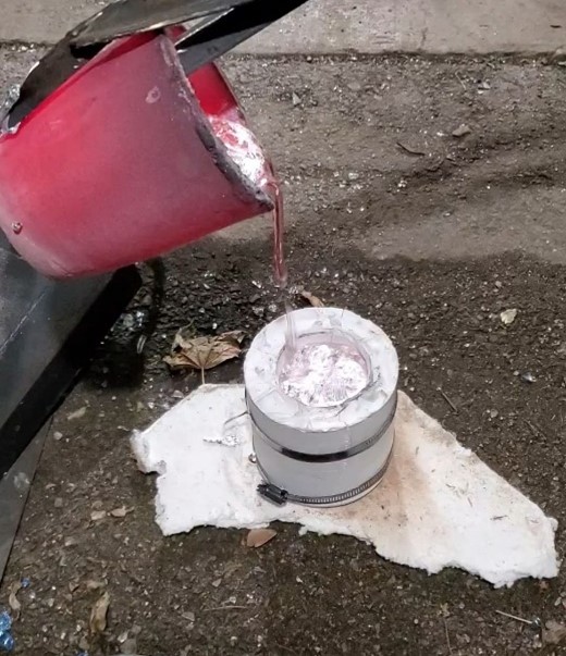

Figures Nine and Ten: Molten Aluminum is Poured into the Plaster Mold

Figure Eleven: Final Aluminum Blow Mold
Process Refinement
In the process of creating the plaster mold from the printed part, the plaster was cracked. Although the cracks were minor and the plaster was still usable, defects at any point in the process will affect the subsequent processes, and a crack in the plaster may adversely affect the surface finish. This may be addressed through post-processing of the final product, however, producing an entirely intact plaster mold will be desirable. In the future, a three-part mold may be produced that would allow for reusability. A reusable mold would eliminate the need to repeat the process of producing the printed part, plaster mold and aluminum mold and simply allow for the creation of multiple molds with less overall material use and work. Future experimentation may be conducted in reducing the infill of the print to further decrease the amount of material that will need to be burned off, while still maintaining precision patterning in the plaster. For certain patterns, a higher infill may be necessary. Further research is required to optimize the printing and casting process. More complex, multi-part aluminum blow molds may also be explored in the next phase of the project.