This project update covers the design updates that were made from the initial prototype once the parts were printed and assembled. In this update, we will detail the challenges we encountered and propose solutions.
1. Challenges
1.1 Structural Design – Degrees of Freedom (DOF)
After assembling the first prototype, several issues concerning the degrees of freedom of the entire system were found.
- Upper Control Arm Connection
The connector, seen in figure 1, was found to be redundant as it increases the DOF of the system without any real need. Therefore, it must either be removed or constrained to maintain the DOF.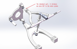
Figure 1: Redundant part shown in the assembled structure - Screw Connector Guide
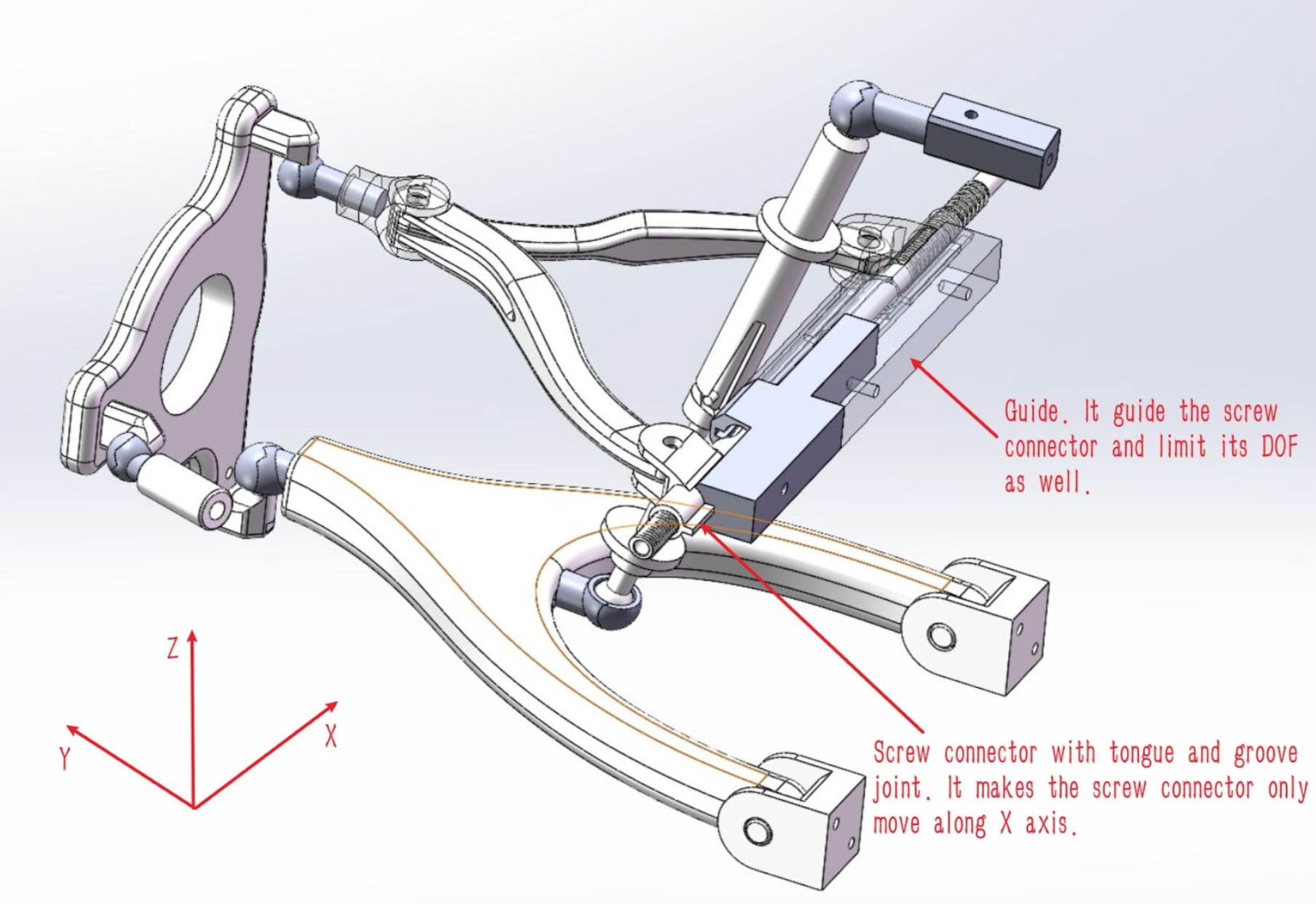
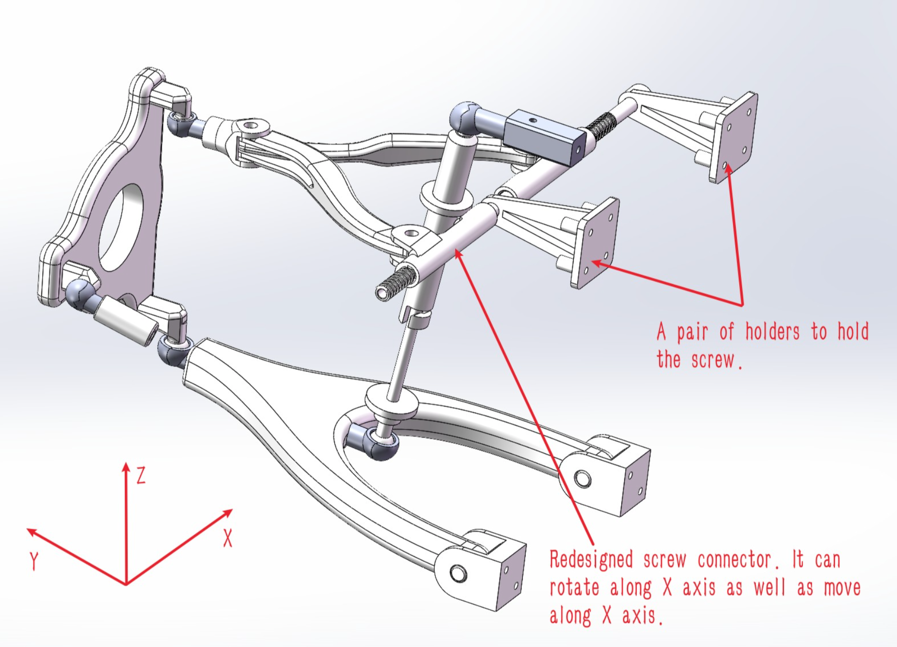
Previously, the system was designed with a guide to hold the screw connector so that it would only move along Ux and limit its DOF, see figure 2. However, after assembly and simulation, it was found that the screw connector also needs a rotational DOF along Ux. The screw guide was replaced with a pair of holders, see figure 3.

1.2 Screw Design
The initial design had a screw with triangle-shaped thread, which would screw into the connector’s threaded insert, see figure 4a. Upon printing, it was found that the poor dimensional accuracy of the part resulted in the screw jamming inside the connector during the rotation. Part inspection showed the following problems.
- The triangular thread’s outer edge is not sharp enough. This lowers the grip between the inner and outer thread, causing it to slip.
- The thread pitch is too small. The printer’s resolution wasn’t high enough to print the thread without it becoming blurry.
- The remaining support material on the screw requires the tolerance of the thread to be increased. However, the triangular threading cannot have a large tolerance without losing its ability to grip the internal threading.
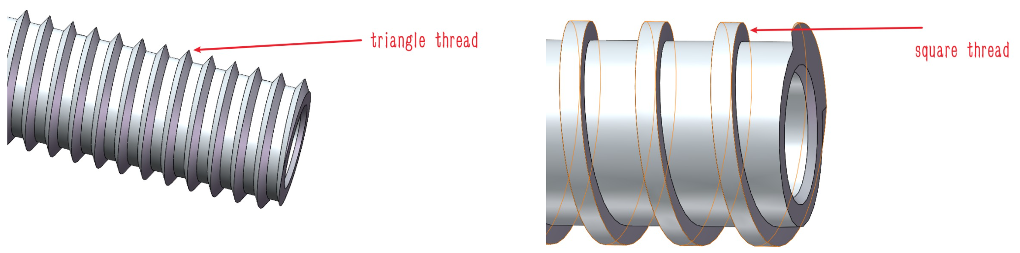
To mitigate these problems, it was decided that the part should be redesigned with square threading, see figure 4b.
2. Results of Printing and Proposed Changes
Prior to printing the parts, critical problems were identified and changes were made to the initial design. After printing, it was observed that some of the proposed solutions worked, however, not all problems were solved. In this section, we discuss some of our results obtained and propose new solutions to both new and persistent problems.
Material properties, surface finish, and dimension accuracy of the printed parts were the biggest concerns during the planning stages. Below is a quick overview of the results of our first print.
- Material Properties
PLA with FFF process: Expected to sustain the weight of the main structure and the normal forces and torsion during operation. So far, no large deformations or material failure has been observed. Clear resin with SLA process: Material provides structural stability.
Overall, the materials selected fulfilled their roles as planned.
- Surface Finish
For the FFF process, the surface finish was as rough as expected. For resin in the SLA process, the surface finish met expectations. Both surfaces are smooth with low friction, despite this, lumps of support material would remain on certain spots. These lumps were particularly problematic for certain parts, such as the ball-joint structure and the threaded parts. Post-processing techniques, such as sanding, were used to solve this problem. Both the ball and socket were sanded smooth, enabling the ball to rotate smoothly. However, in other cases, like the screw structures, support material remaining on the surface was harder to remove, causing further problems (more on this below).
- Dimension Accuracy
Shrinkage during both FFF and SLA processes is the main cause of dimension deviation from the digital model. Quantifying the shrinkage of each part and predicting the real dimension of parts is a difficult task as shrinkage involves several factors such as the printing temperature, the material used, the part shape, and the printer used.
Solutions to the problems encountered are addressed below.
2.1 Part Dimension and Fit
Through trial and error, we empirically figured out a rule of thumb for fit tolerance of parts. The following tables summarize such.
| Objects\basic size (diameter) | 8mm<=, <10mm | 10mm<=, <15mm | >=15mm |
| pin | -0.4mm | -0.5mm | -0.6mm |
| hole | +0.4mm | +0.5mm | +0.6mm |
Table 1: Pin joints clearance fit
| Objects\basic size (diameter) | <15mm | <=15mm, <20mm |
| ball | -0.3 | +0.4 |
| socket | +0.3 | -0.4 |
Table 2: Ball joint clearance fit
| Basic size of axis (diameter) | <6mm |
| hole | +0.3mm |
Table 3: Hole and axis interference fit based on axis
Following these tolerance tables, our prototype was assembled properly.
2.2 Structural Design Changes
Following our initial print and assembly, the following structural changes were made to have the system work properly.
- The Connector
The relative position of the connector to one of the upper control arms was fixed which constrained the connector. Essentially, the connector and the upper arm became a single unit, getting rid of additional DOF. - The Screw Guide
The screw guide was completely removed and replaced with a newly designed structure that allows for fluid rotation of the screw. - New Holder Structure
The new holder structure allows the screw connector to only have linear and rotary DOF along Ux.
2.3 Material Changes
During the assembly process and function trials, we observed that certain movable parts didn’t displace as smoothly as expected even with the addition of a large tolerance for movement. We attribute this to dimensional inaccuracy and the unavoidable limitations of 3D printing processes.
- Fine Detail Inaccuracy
Neither FFF nor SLA processes can produce fine details accurately. For example, in some sections we may require sharp edges and corners, however, the printed part will end up having a filet in those sections due to limitations of the 3D printing process, see figure 5.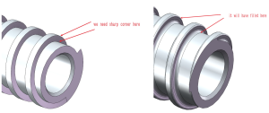
Figure 5: a) Designed part in Solidworks and b) What the printed part looks like The introduction of the filet introduces dimensional inaccuracy and does not allow for a smooth rotation between the internal and external threading. As the screw rotates inside the threaded hole, tolerance is not enough for the thread due to the interference of the filet.
- Residual Support Material
For the SLA process, support material remains attached to the surfaces. Although most can be easily removed, some of it remains on the surface shaped as small lumps. The lumps located inside the threaded hole are particularly difficult to remove, see figure 6. During the rotation of the screw inside the threaded hole, interference occurs between the internal lumps and the screw which inhibits smooth movement.

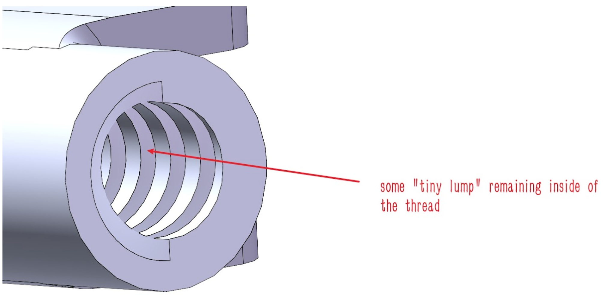
These problems increase the friction between the screw and the hole to the point both parts are vulnerable to operational damage. To find a solution, different design parameters were modified and tested: thread shape (triangular and rectangular shapes), pitch, and depth. However, no solution was found.
It was decided to change the material used for the SLA process. Of the options available, durable resin is the material whose properties are most compatible with the requirements of the prototype. Durable resin has a larger elongation failure rate and a smaller Young’s modulus when compared to clear resin. This allows printed parts to handle smaller deformations easier, while still being resistant to large displacements and high external forces. Besides, it appears to be self-lubricating to an extent, which means a lower friction coefficient. The following table compares these properties to clear resin.
| Material | Young’s modulus (Mpa) | Ultimate tensile strength (Mpa) | Elongation at failure (%) |
| Clear resin | 2800 | 65 | 6.2 |
| Durable resin | 1000 | 28 | 55 |
Table 4: Properties of Clear and Durable Resin
Unlike clear resin, durable resin won’t generate residual powder when parts rub together and its flexibility helps the structure handle deformations when inaccurate dimensions or interference happens, avoiding cracks or breakage.
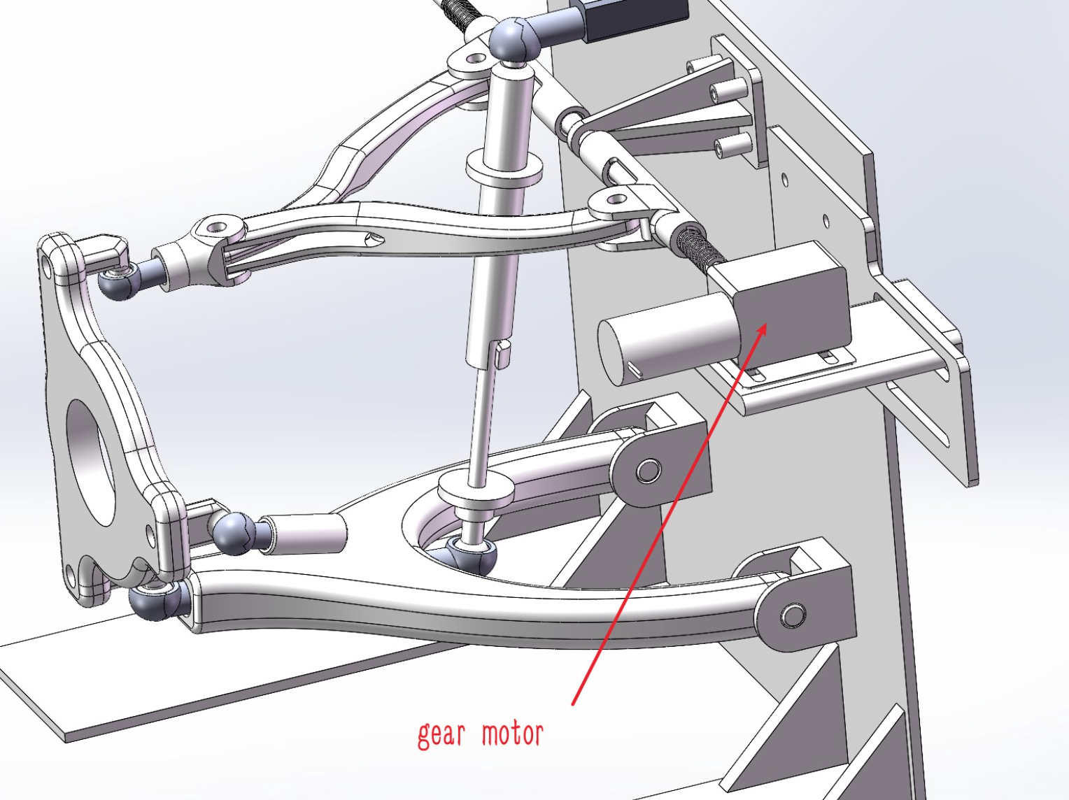
2.4 New Additions to the Design
After discussion, we decided to add an actuator to rotate the screw rather than operating it manually, allowing us to easily demonstrate the change of the tilt angle. Considering the whole structure, we decided to use a 12V gear motor, with enough torque and suitable angular velocity to drive the whole system. The placement of the actuator on the system is shown in the figure 7.