FUSED FILAMENT FABRICATION PART BENDING TESTS
Mihail Yankov, Davis Blanchard, Hannah Walker, and Oliver Ouradnik, University of Wisconsin-Madison, Madison, WI
Abstract
One of the most popular additive manufacturing processes is Fused Filament Fabrication (FFF). This study compares the effect different process parameters have on part strength of FFF manufacturing. The infill orientation, percentage, geometry, and number of wall layers were all tested. The parts were placed in a 3-point bending test and the max strength was recorded. Significant factors include infill geometry, infill percent, and wall layers; infill orientation is not a significant factor. The strongest part had a honeycomb geometry, normal infill orientation, 50% infill, and four wall layers.
Introduction
One of the most commonly used 3D printing methods is fused filament fabrication. One of the biggest factors contributing to the popularity of the FFF method is the ease of operating and maintaining the equipment. This process is also more affordable relative to other printing methods. Additionally, no harsh chemicals are needed which makes the FFF method very safe as well. Companies such as MakerBot and Formlabs began creating small 3D printers and made it easy and cheap to bring 3D printers into the everyday user’s home. This led to an increase in the amount of FFF machines on the market and number of people using these machines. Due to the FFF process’s increasing popularity, many users are searching for a way to optimize the printing process so they can be sure they are printing a strong and high-quality part.
Four factors were tested to find the most impactful parameter and which orientation was strongest. The parameters chosen to test were the infill orientation, infill percentage, infill geometry, and number of wall layers. For the infill geometry the two levels tested were honeycomb and rectilinear patterns. The infill orientations tested were Z and normal. To find the optimal infill percentage, percentages of 25% and 50% were tested. Finally, two wall layers and four wall layers were tested to find the optimal number of wall layers for the FFF method. These parameters are summarized in Table 1. These parameters will be altered over 16 samples and runs to find the how big of an impact each parameter has on the part strength and which parameters are the most significant.
Table 1: Levels of each of the four factors tested.
| Factor | Level 1 (-) | Level 2 (+) |
| A: Infill Geometry | Honeycomb | Rectilinear |
| B: Infill Orientation | Z | Normal |
| C: Infill Percentage | 25% | 50% |
| D: Wall Layers | Two | Four |
This work will focus on optimizing the FFF process by providing insight into how internal part geometry affects the strength of the part.
Materials
The material that was used in the FFF process was polyethylene terephthalate glycol, also known as PETG. PETG is a thermoplastic polymer that provides significant durability and has excellent formability. This material was a good option for the experiments for multiple reasons. First, this material has a very low printing difficulty and a fast printing speed which is important due to the number of samples being printed and the equipment, a Prusa Mini 3D Printer, used to print the samples. Also, PETG has a very good thermal resistance which means there will be virtually no warping to worry about when printing the samples.
From the stress-strain curves for each test, the Young’s Modulus can be calculated. The Young’s modulus of elasticity can be thought of as a measure of how well a part stands up to tension. By using data from the initial portion of the stress-strain curve where the data is linear, Young’s Modulus is calculated by using the following equation:
E = sigma/epsilon (1)
Where sigma is the stress that the sample undergoes and epsilon is the strain that the part undergoes. Figure 1 shows an example of how a Young’s Modulus can be calculated from a stress-strain curve. The data points follow a linear trend that stops at the data points where strain is equal to 21.05 and stress is equal to 24.67 MPa. Inserting these two values into Equation 1 gives this particular sample a Young’s modulus of 1.17 MPa. This process can be repeated for all 16 samples to measure the tensile stiffness of each sample. The Young’s Modulus for each run can be found in Appendix 2.
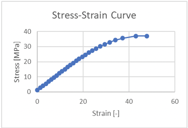
Figure 1. Stress-strain curve example
Geometry
To remove any other factors that would impact the results, each specimen shared the same geometry. The created parts were 4 mm x 4mm x 70 mm. Figure 2 displays the sliced part from the CAD software
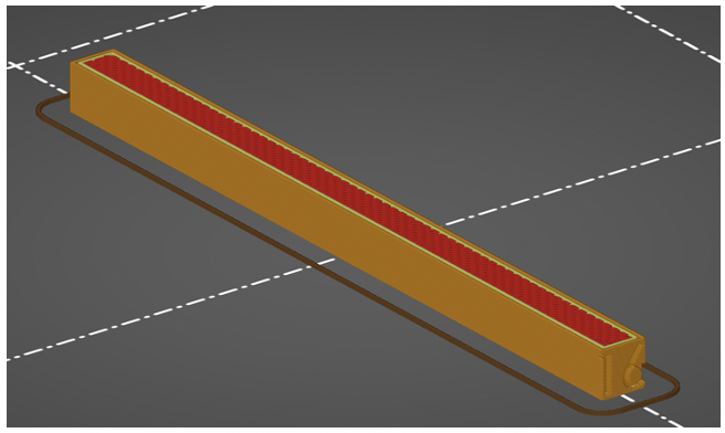
Figure 2. Sliced image of part.
Another important aspect of the geometry is the differences in additive manufacturing parameters. These parameters altered for this test are on the inside of the parts and hard to see from the outside.
Infill Geometry
The infill geometry was altered between honeycomb and rectilinear. The rectilinear pattern is the strongest of the two in the direction of the force but lacks strength in the opposite pattern. A benefit the honeycomb pattern brings is equally strong in all directions[1]. Figure 3 (a) displays the rectilinear infill geometry and Figure 3 (b) displays honeycomb infill orientation.
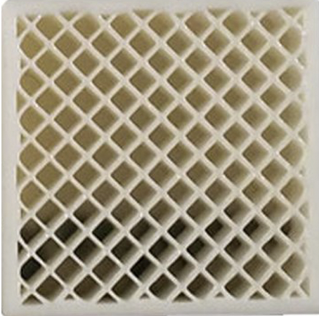
Figure 3 (a). Rectilinear infill orientation.
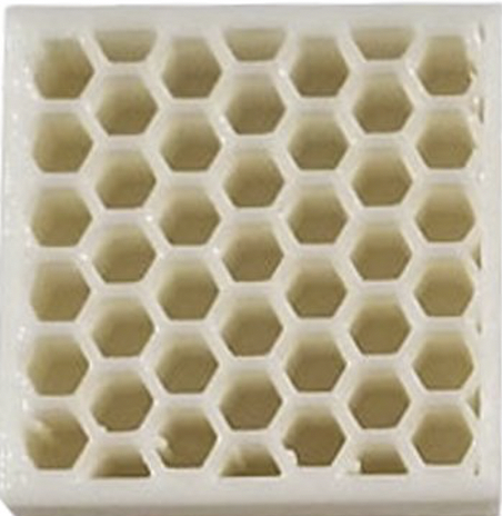
Figure 3 (b). honeycomb infill orientation.
Infill Orientation
Most infill lattices are 2D in nature. The 3D Honeycomb lattice is expected to perform more isotopically than the 2D Rectilinear lattice. The effect of strength due to infill lattice orientation was studied by loading the lattice at a normal or perpendicular angle to the load. This configuration is analogous to loading an ‘I’ beam in the ‘H’ orientation vs. the ‘I’ orientation.
Infill Percent
The infill percent was varied between 25% and 50%. This will directly increase the weight of the specimen while also increasing the strength. Infill percentage does not increase the part strength linearly. It is important to make sure the increase in strength is worth the weight increase. Figure 4 displays the difference changing the infill percentage makes.
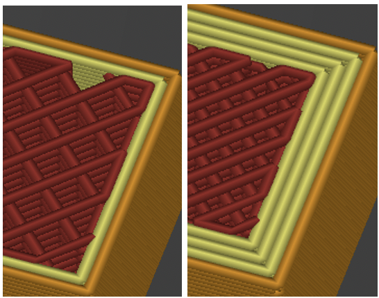
Figure 4. side-by-side of 25% and 50% infill precent.
Wall Layers
The number of wall layers was altered between two and four. This change will have a similar effect on the weight of the specimens, but to less of a degree compared to the infill percent. Figure 5 displays the difference the number of walls will make in the geometry.
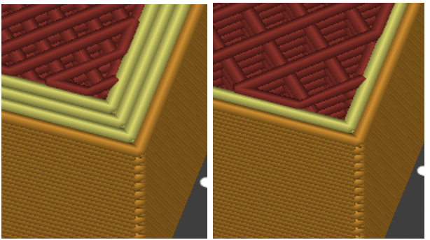
Figure 5. A side-by-side view of 2 and 4 walls.
Procedure
The first step in the testing process is to create the sample. The part was exported from SolidWorks as an .STL file and was imported into PrusaSlicer. Most FFF parts are not printed with 100% infill density. FFF infill typically comprises a lattice containing void space that allows for material and weight savings. The geometry of the infill lattice was then selected by the user.
After each part was created the testing phase started. To test the specimens the parts were placed in a 3-point bending test. ASTM D790-17 Standard Test Methods for Flexural Properties of Unreinforced and Reinforced Plastics and Electrical Insulating Materials Procedure B [2] was used as a reference for the test method. This method recommends a strain rate of 0.1%/min and expects failure around 5% strain. The 3-point bending test works by slowly increasing the force to maintain the set strain rate. To speed up the trials a strain rate of 1%/min was used. A Netzsch DMA Eplexor machine was used to perform the test. The Netzsch machine has a 500 N load cell and a 3.0 mm elongation sensor. A static load sweep was performed with the sweep beginning at 0 N with a maximum force of 400 N, or until the force cannot increase any more. Figure 6 displays how each part is set up in the machine.
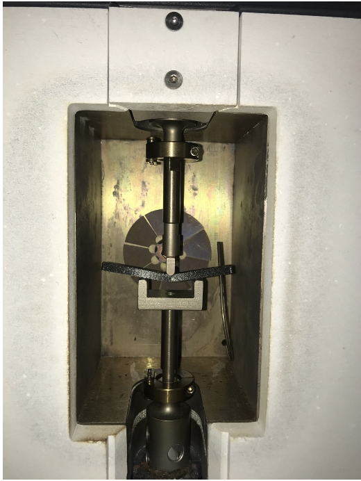
Figure 6. Image of the part During the test [3].
Inputting the part geometry into the Netzsch machine, the software can provide a stress-strain curve from the data, from this curve both the Ultimate Tensile Strength and Young’s Modulus can be found and compared. This is the final step in the testing process before the data is analyzed.
Results and Discussion
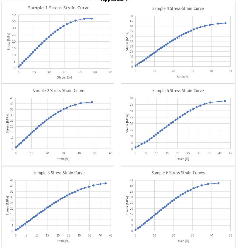
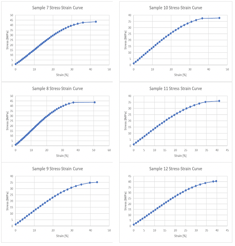
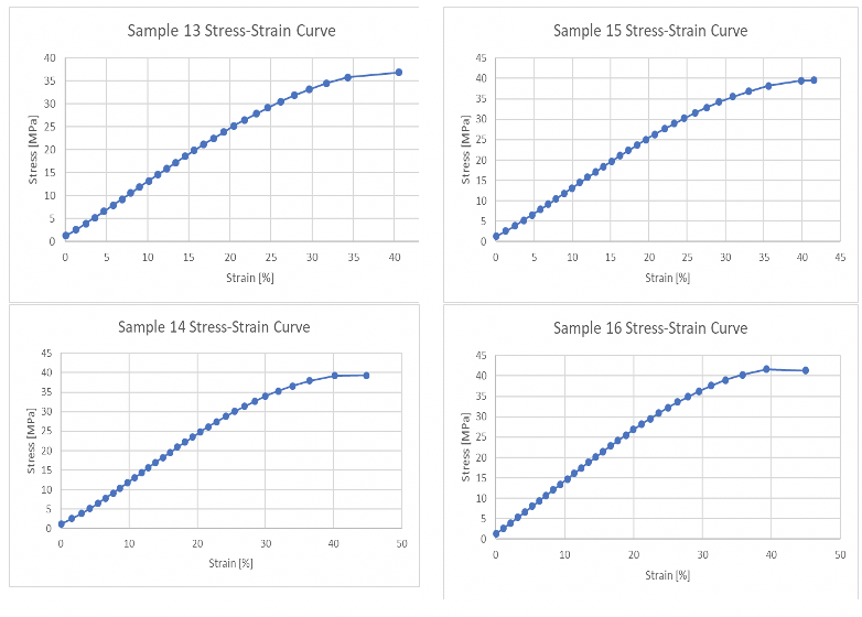
After the Netzsch machine provides a stress-strain curve the data from it can be recorded. Figure 7 displays the stress-strain curve for the first trial, honeycomb, z orientation, 25% with 2 layers. The stress-strain curves for all 16 trials can be found in Appendix 4.
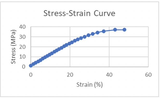
Figure 7. Stress-strain curve from Netzsch machine.
Using the provided stress-strain curve, the largest stress value can be recorded. It is also worth noting that the trial fails at a much larger strain % than Procedure B expects [2]. Each trial fails around 35-45% strain; this is because the chosen PETG material is extremely flexible and never actually reaches fracture.
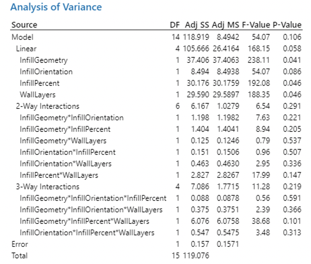
Once each trial was run and the max stress was recorded the main effects of the parameters were calculated. The main effect measures the impact a single independent variable has on a dependent variable regardless of other factors. A full factorial analysis provided insights on effect and interaction significance.
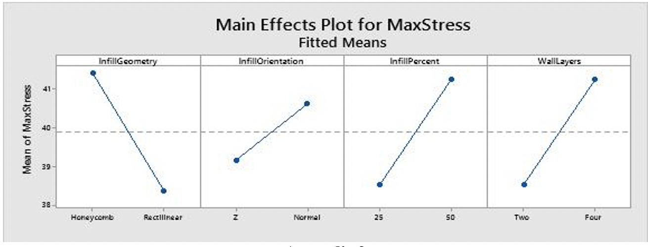
Using the main effect, the figures in Appendix 1 were created. From the graph the most important orientations of each parameter were a honeycomb infill geometry, a normal infill orientation, a 50% infill percentage and four wall layers. This matches up with the data as the largest maximum stress came from the trial that had these exact specifications. The infill orientation had the smallest impact on the part strength. To display the effect each parameter and combination has a Pareto chart was created. A Pareto chart identifies and ranks the most significant factors. Figure 8 displays the Pareto chart for the data.
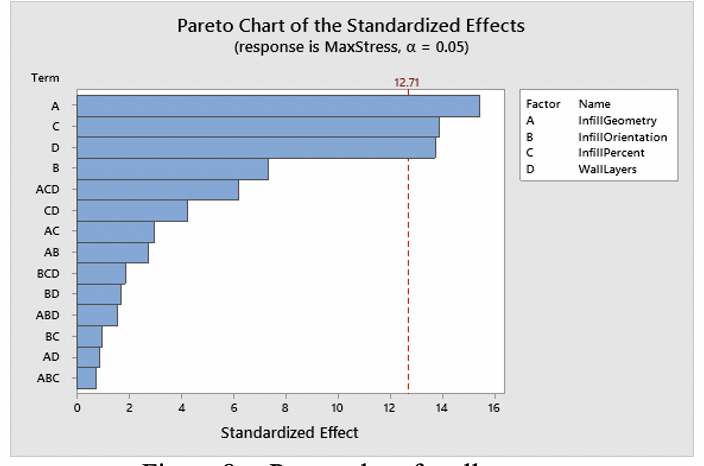
Figure 8.a. Pareto chart for all tests
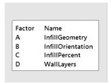
Figure 8.b. legend of the parameters for Figure 8.a.
When looking at the Pareto chart, the three most impactful parameters are Infill Geometry, Infill Percentage, and number of wall layers. These factors had around 6 points larger of an effect. The infill geometry effect is 15, which is double what the infill orientations effect is. The wall layers and infill percentage are expected to increase as they get bigger as there is more material being used. Both these parameters will increase the weight of the part as they are increased. While the weight does increase the impact the parameters have on the max strength, they are still valuable to look at. The infill geometry and orientation are geometry based. These have less of an effect on the weight, it is testing the strongest way to layout the infill of the part.
Conclusions
After running all of the tests and analyzing the data, the team was able to see which factors that were tested had the biggest impact on the strength of a fused filament fabrication part. The pareto chart that was created shows a ranking of how significant each factor was. Infill geometry, infill percent and the number of wall layers had by far the most significant impact while infill orientation had the smallest impact of the factors tested. Appendix 2 shows a table of how each test was set up and the factors that were used. Additionally, the table shows the maximum stress each sample was able to undergo as well as the Young’s modulus for each sample which was calculated by using the stress-strain curve for each run.
Appendix 2 shows that the two samples that performed the best were samples 7 and 8. Both of these tests were ran with a honeycomb infill geometry, a normal infill orientation, and an infill percentage of 50. The tests differ with sample 7 had two wall layers while sample 8 had four wall layers. Nonetheless, the difference in wall layers did not have a big impact as both samples had the highest maximum stress and Young’s modulus, making those factor combinations the best for improving the strength of an FFF part.
Appendix 1
Appendix 2
| Sample | Infill Geometry | Infill Orientation | Infill Percent | Wall Layers | Max Stress | Young’s Modulus |
| 1 | Honeycomb | Z | 25 | Two | 37.06995 | 1.186 |
| 2 | Honeycomb | Z | 25 | Four | 41.54862 | 1.314 |
| 3 | Honeycomb | Z | 50 | Two | 42.26445 | 1.346 |
| 4 | Honeycomb | Z | 50 | Four | 42.94049 | 1.325 |
| 5 | Honeycomb | Normal | 25 | Two | 37.79614 | 1.176 |
| 6 | Honeycomb | Normal | 25 | Four | 42.55035 | 1.348 |
| 7 | Honeycomb | Normal | 50 | Two | 43.42604 | 1.454 |
| 8 | Honeycomb | Normal | 50 | Four | 43.69052 | 1.453 |
| 9 | Rectilinear | Z | 25 | Two | 35.15317 | 1.138 |
| 10 | Rectilinear | Z | 25 | Four | 37.73595 | 1.283 |
| 11 | Rectilinear | Z | 50 | Two | 36.00515 | 1.249 |
| 12 | Rectilinear | Z | 50 | Four | 40.50784 | 1.304 |
| 13 | Rectilinear | Normal | 25 | Two | 36.89379 | 1.217 |
| 14 | Rectilinear | Normal | 25 | Four | 39.31995 | 1.224 |
| 15 | Rectilinear | Normal | 50 | Two | 39.56645 | 1.253 |
| 16 | Rectilinear | Normal | 50 | Four | 41.64037 | 1.318 |
Appendix 3
Appendix 4
References
- Tyson, Ed, How to use 3D print Infill Settings, (2015)
- ASTM International. D790-17 Standard Test Methods for Flexural Properties of Unreinforced and Reinforced Plastics and Electrical Insulating Materials. West Conshohocken, PA; ASTM International,2017.doi:ttps://doi.org/10.1520/D0790-17
- self-made image