What is being done and why?
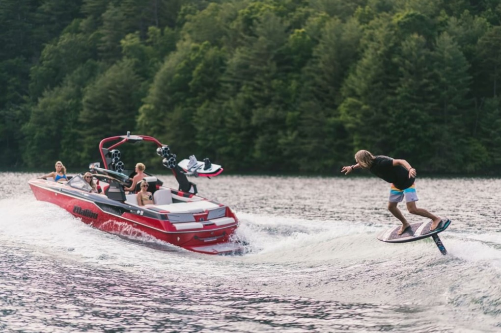 Figure 1: Hydrofoil used to ride a small wave. [1]
Hydrofoils are a unique way of reducing drag on water vessels. In simple terms, they are wings designed to be used in water. Like airplane wings, they create lift from the difference in fluid velocity above and below the foil and by flow deflection. They have been put to use on boats, sailboats, paddleboards, and everything in between. Of special interest for this project is use on personal surfboards- as seen in Figure 1. Approximately 30 years ago, the first metal hydrofoils were attached to a 3-foot-long mast under the board. This allowed riders to ‘fly’ above the water with very little drag. These metal foils were heavy and expensive. In recent years, companies have begun to sell Carbon Fiber kits- like shown in Figure 2- that are lighter than original models but still expensive (upwards of $1000) [2].
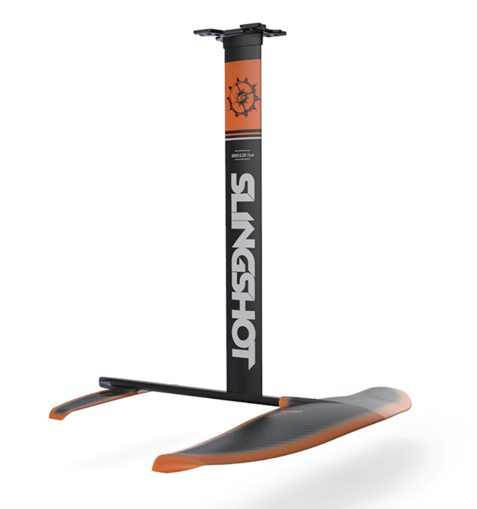
Figure 2: Carbon fiber foil and aluminum mast. [2]
The goal of this project is to produce a hydrofoil and mast assembly using additive manufacturing as the primary manufacturing method. This will serve as a proof of concept for a cost-effective, customizable, and lightweight hydrofoil that can be produced with a standard 3D printer and common tools. The cost of materials for our design will be significantly less than that of a Carbon Fiber or metal hydrofoil. This could open opportunities for individuals with a smaller budget. Furthermore, the low cost and short time-to-build qualities of additive manufacturing could allow people to build many custom foils for varying conditions.
Preliminary designs and manufacturing considerations
To gain an understanding of the project, we began by creating a CAD model of our proposed design. The assembly of 5 parts can be seen in Figure 3.
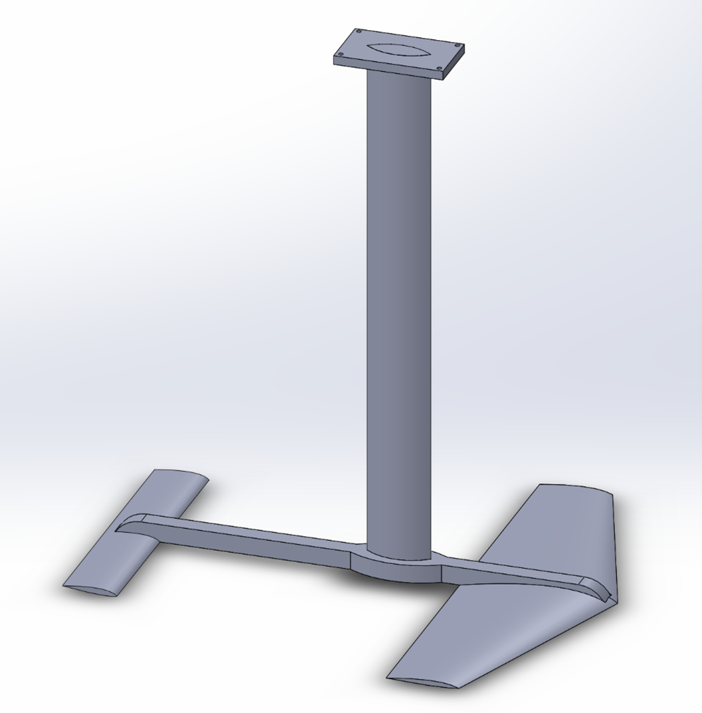
Figure 3: Preliminary assembly, modeled in Solidworks
The CAD model is based on the basic shape and size of carbon fiber hydrofoils currently in the market. The model illustrates several challenges of the project. First, some of the parts are much too large to be printed in one piece (for example, the mast is 30 inches long). To show that a full-size hydrofoil can be 3D printed, we will have to devise a way to make parts in several pieces that can be put together after printing. Second, the shape and application of the parts will make print orientation very important. Both strength and resolution will be affected by the print orientation.
A smooth, uniform surface is desirable to reduce friction with the fluid. A vat polymerization process like solid ground curing, stereolithography, or digital light synthesis would give the best surface quality. However, the only SLA printers available are the Form 2 and Form 3. Their build volume is 5.7” x 5.7” x 7.3”. This will not be large enough to print the hydrofoil even with a modular design. For this reason, we will use FFF printers. With a build volume of 14” x 10” x 14” and a layer thickness of 127 – 330 microns, the Stratasys printer might be our best option.
Since the hydrofoil is meant to be aerodynamic, the parts must be somewhat thin. This will emphasize the importance of print orientation as it relates to strength. Without proper layer direction, the wings and mast might not be strong enough to support a person.
The material used will also be important. Firstly, its solvent compatibility with saltwater and water must be considered. The plastic cannot weaken in water or absorb water weight. The material must also be stiff enough for the wings to maintain their ideal shape. Finally, the material must be strong enough to support the weight of a person without using an un-aerodynamic amount of material.
Proposed first steps
The process to produce a hydrofoil will require research and iteration. The first task will be to develop the desired design, primarily the shape of the foils. Since we are focusing on additive manufacturing in relation to hydrofoils, we will not be spending time developing a unique shape. A known hydrofoil design and/or common NACA airfoil will be used.
With an idea of the desired final shape, we will focus on experimenting with the two biggest variables: print orientation and modular design. The mast of the hydrofoil will provide a perfect testbed. Since it is thin and long, the print orientation will be important for strength. The print orientation will also affect the smoothness in the direction of fluid flow. If we cannot reach an acceptable smoothness straight out of the printer, we may have to experiment with post-processing techniques. Sanding the outer surface could be a simple solution. Being 30 inches long, the mast will not be printed in one piece. Before our first project update, we will experiment with print orientation and methods to print the mast in multiple pieces. The results of these experiments will translate to printing the foils and other parts.
References
[1] “Malibu Boats (@malibuboats) • Instagram photos and videos.” https://www.instagram.com/p/CLXfuPojLlg/ (accessed Feb. 27, 2021).
[2] “2021 Slingshot Hover Glide FWING V1 Hydrofoil.” https://www.mackiteboarding.com/2021-slingshot-hover-glide-fwing-v1-hydrofoil/?gclid=CjwKCAiAm-2BBhANEiwAe7eyFOFV2LXmB-yEqlQYBiam9n0tFwFnumD1ehH7bJezbk2KcNxWslqzUBoCwygQAvD_BwE (accessed Feb. 27, 2021).